Page 191 of 796
02-32
2) Timing Chain and Gear
(1) Timing chain
Simple layout: optimized timing, enhanced
NVH
Single stage layout: minimized chain load
The brass link on crankshaft is at symmetric
position of that on camshaft. -
-
-
Chain upper bush
- Single bush type (112 EA)
Chain lower bush
- Single bush type (60 EA)
(2) Tensioner
Tensioner adjusts the chain tension to keep it tight during engine running. This reduces the wear in
guide rail and spoke.
Operating principle
- Use the spring tension in tensioner and hydraulic pressure
Tensioner type
- Compensation and impact absorbing
Static and dynamic force
- Spring + Hydraulic pressure 1.
2.
3.
Plunger
HousingSpring
Check valve
Hydraulic tensioner assembly ▶
Page 192 of 796
02-330000-00
Clamping guide railTensioner guide rail
(3) Mechanical Tensioner Assembly
Operating principle
- Use only spring tension
Tensioner type
- Compensation and impact absorbing
Static and dynamic force
- Spring
(4) Guide rail
The guide rail is used for optimizing the movement of chain drive system. And it also prevents the
chain from contacting each other when the chain is loose, and reduces the chain wear.
The guide rail is made of plastic, nylon, Teflon, etc. The guide rail is specially required when the
distance between two spokes is too great. It pushes the chain with constant force so that the chain can
work smoothly. The guide rail is fitted by pins.
Page 195 of 796
02-36
Oil pan sassembly
8. OIL PAN
The oil pan in D20DTR engine improves the NVH. Especially, the oil draining is much easier than
before.
Components ▶
Page 200 of 796
02-410000-00
1) Piston
(1) Overview
Piston assembly contains piston, #1 ring, #2
ring, oil ring, piston pin and snap ring. The
expansion energy from engine is transferred to
the crankshaft through connecting rod to
convert the linear movement to rotating energy.
(2) Layout
#1 ring
Oil ring
Snap ring
#2 ring
Material:
B2+
Skirt coating:
MoS2
Piston cooling gallery
for connecting rod
Wide bawl type (CR 16.5)
Cooling jet
Page 212 of 796

03-52210-01
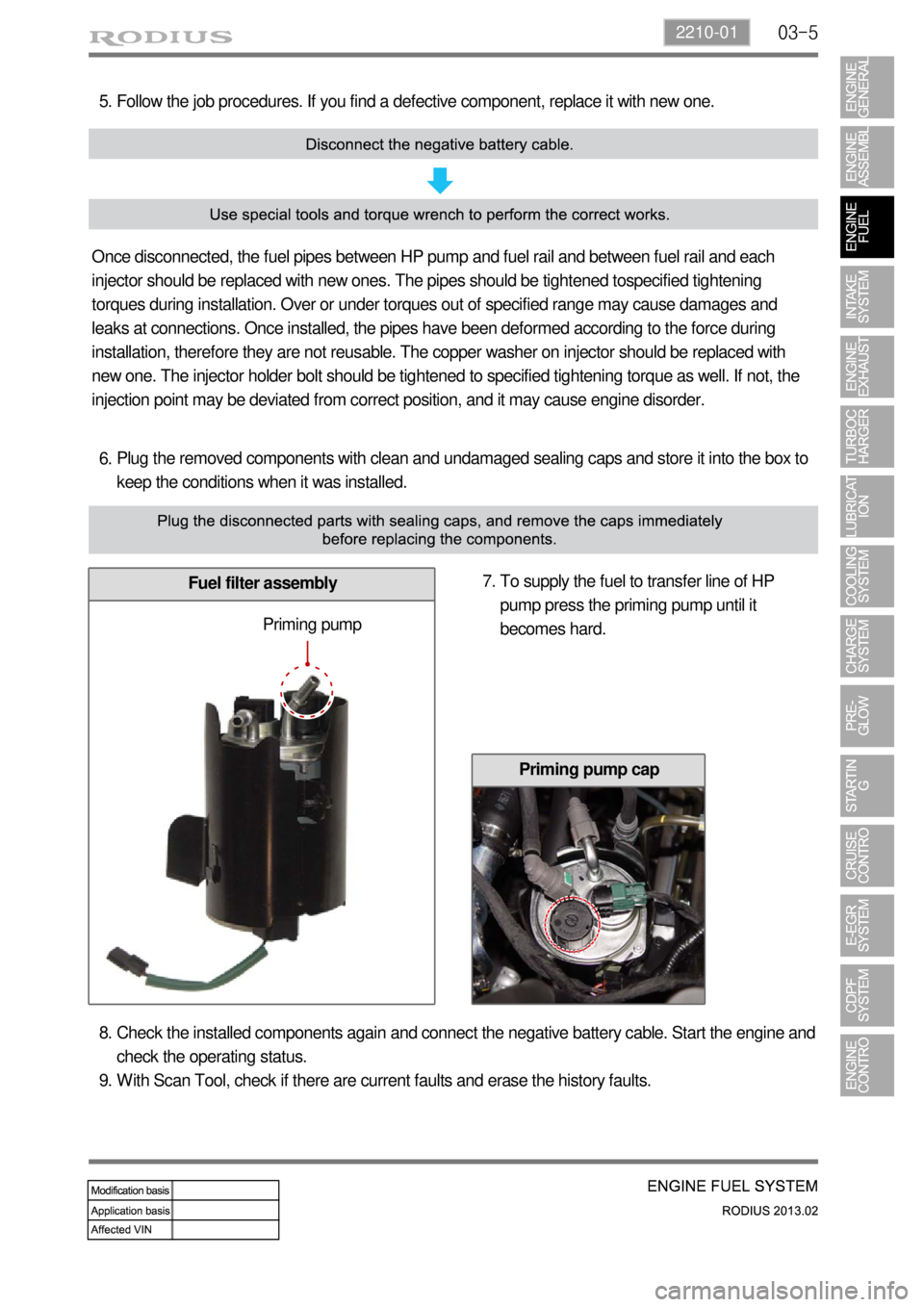
Plug the removed components with clean and undamaged sealing caps and store it into the box to
keep the conditions when it was installed. 6.
Fuel filter assembly
Follow the job procedures. If you find a defective component, replace it with new one. 5.
Once disconnected, the fuel pipes between HP pump and fuel rail and between fuel rail and each
injector should be replaced with new ones. The pipes should be tightened tospecified tightening
torques during installation. Over or under torques out of specified range may cause damages and
leaks at connections. Once installed, the pipes have been deformed according to the force during
installation, therefore they are not reusable. The copper washer on injector should be replaced with
new one. The injector holder bolt should be tightened to specified tightening torque as well. If not, the
injection point may be deviated from correct position, and it may cause engine disorder.
To supply the fuel to transfer line of HP
pump press the priming pump until it
becomes hard. 7.
Priming pump
Check the installed components again and connect the negative battery cable. Start the engine and
check the operating status.
With Scan Tool, check if there are current faults and erase the history faults. 8.
9.
Priming pump cap
Page 227 of 796

03-20
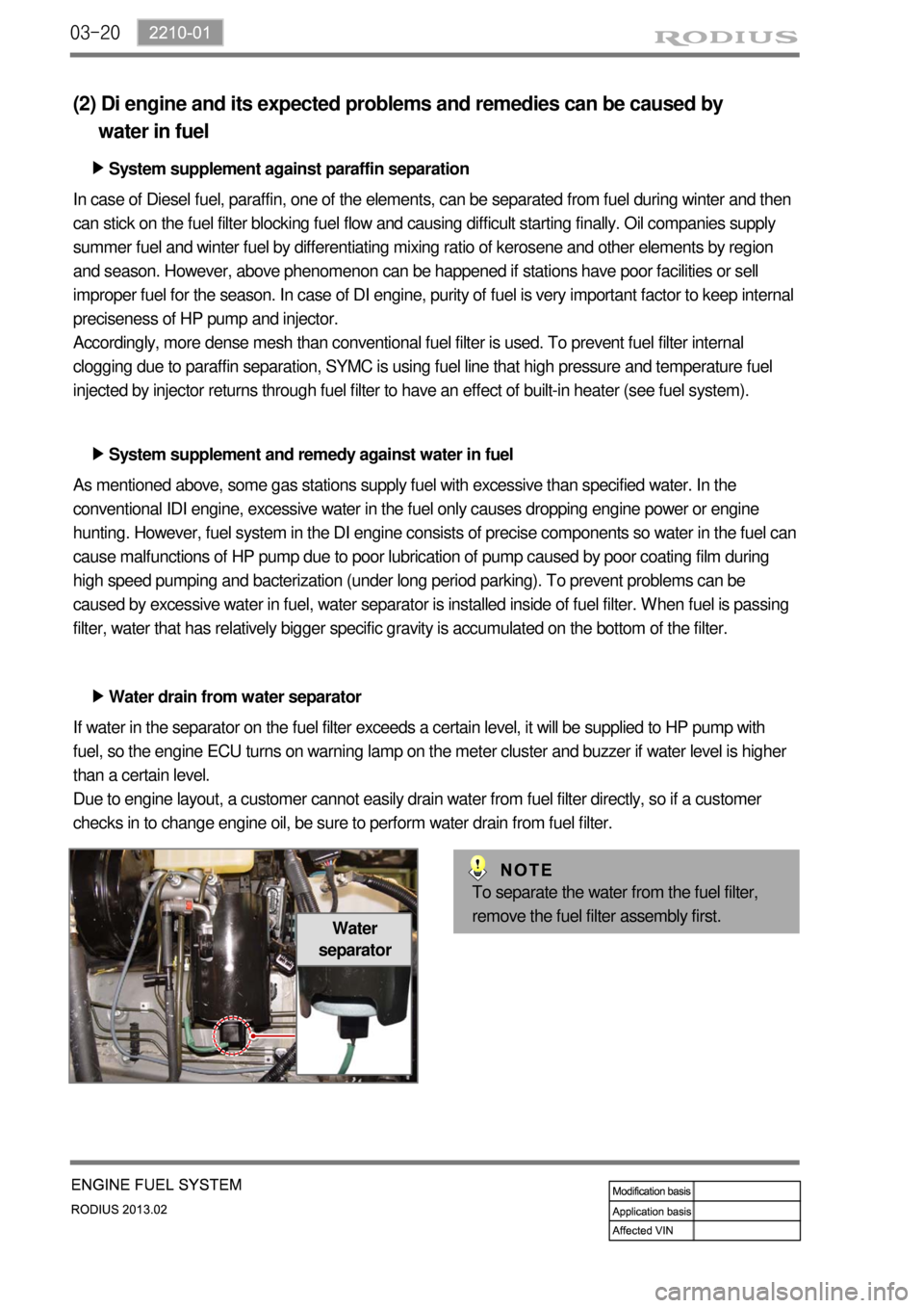
Water
separator
(2) Di engine and its expected problems and remedies can be caused by
water in fuel
System supplement against paraffin separation ▶
In case of Diesel fuel, paraffin, one of the elements, can be separated from fuel during winter and then
can stick on the fuel filter blocking fuel flow and causing difficult starting finally. Oil companies supply
summer fuel and winter fuel by differentiating mixing ratio of kerosene and other elements by region
and season. However, above phenomenon can be happened if stations have poor facilities or sell
improper fuel for the season. In case of DI engine, purity of fuel is very important factor to keep internal
preciseness of HP pump and injector.
Accordingly, more dense mesh than conventional fuel filter is used. To prevent fuel filter internal
clogging due to paraffin separation, SYMC is using fuel line that high pressure and temperature fuel
injected by injector returns through fuel filter to have an effect of built-in heater (see fuel system).
System supplement and remedy against water in fuel ▶
As mentioned above, some gas stations supply fuel with excessive than specified water. In the
conventional IDI engine, excessive water in the fuel only causes dropping engine power or engine
hunting. However, fuel system in the DI engine consists of precise components so water in the fuel can
cause malfunctions of HP pump due to poor lubrication of pump caused by poor coating film during
high speed pumping and bacterization (under long period parking). To prevent problems can be
caused by excessive water in fuel, water separator is installed inside of fuel filter. When fuel is passing
filter, water that has relatively bigger specific gravity is accumulated on the bottom of the filter.
Water drain from water separator ▶
If water in the separator on the fuel filter exceeds a certain level, it will be supplied to HP pump with
fuel, so the engine ECU turns on warning lamp on the meter cluster and buzzer if water level is higher
than a certain level.
Due to engine layout, a customer cannot easily drain water from fuel filter directly, so if a customer
checks in to change engine oil, be sure to perform water drain from fuel filter.
To separate the water from the fuel filter,
remove the fuel filter assembly first.
Page 230 of 796
03-232210-01
T-MAP sensor
Measuring booster pressure
and temperatureFuel rail assembly
Relieving the pulsation.
Measuring the fuel pressure.
Distributing the fuel to injectors.
Plunger type HP pump (1,800 bar)
Vane type LP pump (6 bar)
Accelerator pedal position
sensor
Detecting driver's intention for
speed up/down
Fuel filter assembly
Supplying clean fuel/fuel
heating/water separation by
priming pump
High pressure pump
Generating high pressurized fuel
and supplying it according to engine
rpm, required volume, required
pressure
Page 234 of 796
04-31719-00
1. SPECIFICATIONS
Shorten the service interval under severe conditions such as driving on a dusty road or off-road. *
Unit Description Specification
Air cleaner elementFilter type Dry, filter element
Initial resistance Max. 300 mmAq
Service interval EU: Change every 20,000 km
GEN: Change every 15,000 km
Air cleaner assemblyWeight 2.36kg
Operating temperature-30 ~ 100℃
IntercoolerRadiation over 13,000 Kcal
Pressure loss at turbocharger below 90 mmHg
Cooling type Air cooled type
Core size 450W*130H*70T
Core type C/FIN