2013 SSANGYONG NEW ACTYON SPORTS cruise control
[x] Cancel search: cruise controlPage 179 of 751

12-118510-23
5) Normal Cancellation of the Cruise Control
The cruise control system will be canceled when one or more items of the following conditions are
applied;
When the brake pedal is depressed or When ESP is activated.
When the cruising speed is downed less than 34 km/h
When applying the parking brake during driving.
When using the clutch in order to shift (M/T only). 1.
2.
3.
4.
Keep the main cruise control switch in the neutral position when not using the cruise control.
Page 180 of 751

12-12
Do not move the shift lever to Neutral position while driving with the cruise control turned on.
Otherwise, it may result in system malfunction or accidents.
Always be prepared to use the brake or accelerator pedal for safe driving while the cruise control
system is running.
The actual speed can be different from the set speed momentarily when driving on a uphill or
downhill. So, it is recommended to disable the cruise control function on a uphill or downhill. hen
driving on a steep hill use the engine brake and foot brake properly to protect the vehicle system
and for a safe driving.
Ensure that the safe distance is maintained and use the brake pedal if needed. 1.
2.
3.
4.
(1) Abnormal Cancellation of the Cruise Control
When the rapid deceleration is applied without braking.
When the rapid acceleration is applied without acceleration pedal intervention.
When the cruise control lever is faulty.
When the brake switch and the brake light switch input signal are implausible. 1.
2.
3.
When the cruise control function is cancelled abnormally or intermittent problems occur, stop the vehicle
and turn off the ignition switch and remove the key to reset the system. After a while, turn on the ignition
switch again to operate the cruise control system.
Page 203 of 751

15-30000-00
1. ENGINE DATA LIST
Data Unit Value
Coolant temperature℃ 0.436 V (130℃) to 4.896 V (-40℃)
Intake air temperature℃ -40 to 130℃ (varies by ambient air
temperature or engine mode)
Idle speed rpm750 ± 20
Engine load % 18~25%
Mass air flow kg/h 16 to 25 kg/h
Throttle position angle°TA 0° (Full Open) to 78° (Close)
Engine torque Nm varies by engine conditions
Injection time ms 3 to 5ms
Battery voltage V 13.5 V to 14.1 V
Accelerator pedal position 1 V 0.4. to 4.8V
Accelerator pedal position 2 V 0.2 to 2.4 V
Throttle position 1 V 0.3 to 4.6 V
Throttle position 2 V 0.3 to 4.6 V
Oxygen sensor mV 0 to 5 V
A/C compressor switch 1=ON / 0=OFF -
Full load 1=ON / 0=OFF -
Gear selection (A/T) 1=ON / 0=OFF -
Knocking control 1=ON / 0=OFF -
Brake switch 1=ON / 0=OFF -
Cruise control 1=ON / 0=OFF -
Page 211 of 751

15-110000-00
2) ECU Control
(1) Function
a. ECU Function
ECU receives and analyzes signals from various sensors and then modifies those signals into
permissible voltage levels and analyzes to control respective actuators.
ECU microprocessor calculates injection period and injection timing proper for engine piston speed and
crankshaft angle based on input data and stored specific map to control the engine power and emission
gas.
Output signal of the ECU microprocessor drives pressure control valve to control the rail pressure and
activates injector solenoid valve to control the fuel injection period and injection timing; so controls
various actuators in response to engine changes. Auxiliary function of ECU has adopted to reduce
emission gas, improve fuel economy and enhance safety, comforts and conveniences. For example,
there are EGR, booster pressure control, autocruise (export only) and immobilizer and adopted CAN
communication to exchange data among electrical systems (automatic T/M and brake system) in the
vehicle fluently. And Scanner can be used to diagnose vehicle status and defectives.
<00760097008c00990088009b00900095008e0047009b008c00940097008c00990088009b009c0099008c0047009900880095008e008c00470096008d0047006c006a007c00470090009a0047009500960099009400880093009300a000470054005b005700
47009b009600470052005f005c00b6006a004700880095008b> protected from factors like oil,
water and electromagnetism and there should be no mechanical shocks.
To control the fuel volume precisely under repeated injections, high current should be applied instantly
so there is injector drive circuit in the ECU to generate necessary current during injector drive stages.
Current control circuit divides current applying time (injection time) into full-in-current-phase and hold-
current-phase and then the injectors should work very correctly under every working condition.
b. Control Function
Controls by operating stages
To make optimum combustion under every operating stage, ECU should calculate proper injection
volume in each stage by considering various factors.
Starting injection volume control
During initial starting, injecting fuel volume will be calculated by function of temperature and engine
cranking speed. Starting injection continues from when the ignition switch is turned to ignition
position to till the engine reaches to allowable minimum speed.
Driving mode control
If the vehicle runs normally, fuel injection volume will be calculated by accelerator pedal travel and
engine rpm and the drive map will be used to match the drivers inputs with optimum engine power. -
-
-
Page 391 of 751

04-8
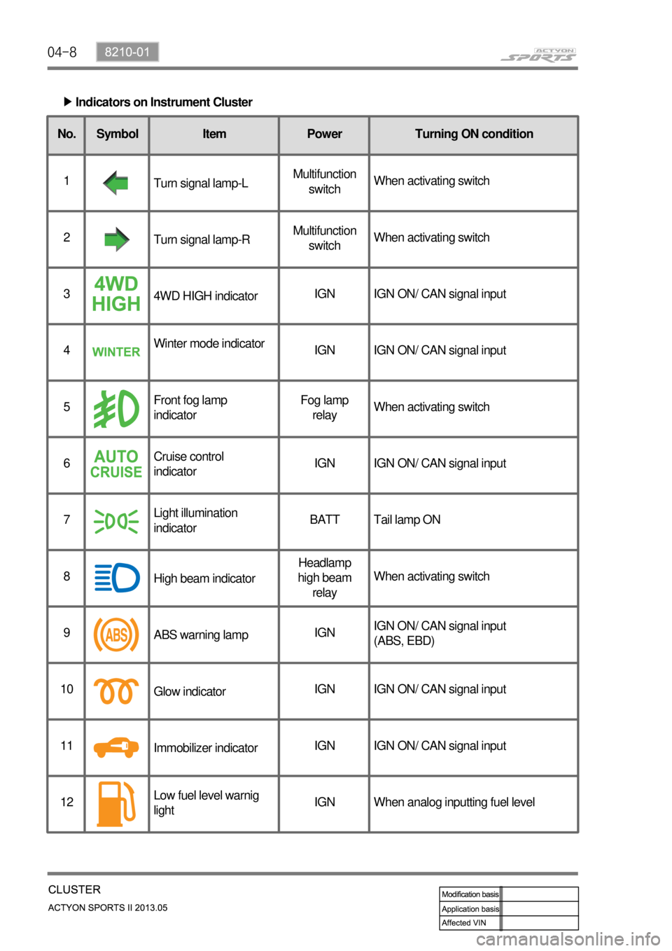
Indicators on Instrument Cluster ▶
No. Symbol Item
1
Turn signal lamp-L
2
Turn signal lamp-R
3
4WD HIGH indicator
4Winter mode indicator
5Front fog lamp
indicator
6Cruise control
indicator
7Light illumination
indicator
8
High beam indicator
9
ABS warning lamp
10
Glow indicator
11
Immobilizer indicator
12Low fuel level warnig
lightPower Turning ON condition
Multifunction
switchWhen activating switch
Multifunction
switchWhen activating switch
IGN IGN ON/ CAN signal input
IGN IGN ON/ CAN signal input
Fog lamp
relayWhen activating switch
IGN IGN ON/ CAN signal input
BATT Tail lamp ON
Headlamp
high beam
relayWhen activating switch
IGNIGN ON/ CAN signal input
(ABS, EBD)
IGN IGN ON/ CAN signal input
IGN IGN ON/ CAN signal input
IGN When analog inputting fuel level
Page 404 of 751

04-218210-01
ABS Warning Light
This warning light comes on
when the ignition switch is turned
to "ON" position and should go
out if the system is normal.
The vehicle with ABS performs
self-diagnosis. During this
diagnosis, brake pedal vibration
and noise may be apparent
when the driving motors
discharges the hydraulic
pressure from the internal
hydraulic device.4WD IndicatorLow Fuel Level
Warnig Light
This warning light
comes on when the
fuel will soon be
exhausted. The time
it takes turn on,
however, varies
according to the
gradient of the
vehicle.
4WD HIGH Indicator
The lamp blinks momentarily during
the change of driving mode.
4WD LOW Indicator
The lamp blinks momentarily during
the change of driving mode.
4WD CHECK Warning Light
This indicates that there is something
wrong in the transfer case system.
(check the system) -
-
-
Auto Cruise Control
Indicator
Operating the cruise
control switch turns on
the indicator lamp to
indicate the cruise
control system is
activated.
Water Separator Warning Light
This lamp comes on to warn the driver of
water in the fuel tank which causes the loss
of engine power. When a certain amount of
water is accumulated, the lamp comes on
and a chime sounds.
Engine CHECK Warning Light
This warning light comes on when the
ignition switch is turned to "ON"
position and should go out if the
system related to engine control is
normal.
This comes on when different sensors
and devices related to engine control
are defective.
Winter Mode
Indicator
Pressing the "W" side of the
automatic transmission mode
selector switch switches the driving
mode to winter mode and turns on
the indicator lamp.
Use this mode to drive off smoothly
on icy and slippery roads.
Charge Warning Light
This warning light comes on when the
ignition switch is turned on and go off when
the engine is started.
If this light doesn't go off after engine starting,
it means there is a malfunction in the system.
Engine Hood Open Warning Light
When the engine hood is open, this light
comes on to inform the driver.
Hazard Indicator
This indicator blinks when the
hazard warning flashers are
switched on.
Page 468 of 751

01-22
Winter Mode (W) ▶
Low Range Driving Mode ▶
Warm Up Mode ▶ When the Winter mode is selected, the second gear is engaged to start off the vehicle easily to prevent
wheel spin on slippery surfaces and WINTER mode indicator comes ON. The first gear is not available
in this mode.
When the vehicle is in 4L driving mode, the transmission uses a different shift mode to optimize the low
range driving. Similar to Winter mode, the first gear is not available.
This mode is normally used when the transmission oil temperature is below 20°C.
<007b008f008c0047009b009600990098009c008c0047008a00960095009d008c0099009b008c00990047008a0088009500950096009b00470089008c004700930096008a0092008c008b0054009c009700470089008c00930096009e00470059005700b600
6a0047009b00960047009700990096009d0090008b008c0047>the warming up process of
transmission.
Hot Mode ▶
<0070008d0047009b008f008c0047009b009900880095009a00940090009a009a00900096009500470096009000930047009b008c00940097008c00990088009b009c0099008c00470090009a00470089008c009b009e008c008c0095004700580058005700
b6006a004700880095008b00470058005b005c00b6006a0053> the system provides the cooling
and reduces the load to the transmission. This is called Hot Mode.
Above 110°C:
Above 130°C:
Above 145°C: -
-
-
In Hot Mode, any of shift mode is not available.
Cruise Control ▶
When the cruise control is activated, the engine ECU requests the downshift to increase the engine
brake effect.PWM fan ON
the engine torque is reduced and WINTER indicator is blinking
the transmission is held in Neutral (N) gear until the oil temperature falls below
120°C (Final protection)