Page 520 of 751
04-4
1. OVERVIEW
The hydraulic clutch transmits the force required to operate the clutch pedal to the concentric slave
cylinder fitted to the clutch housing as a hydraulic pressure.
(The hydraulic pressure is transmitted in the following order: Clutch pedal - Clutch master cylinder -
Clutch pipe - Clutch damper - Clutch pipe and hose - Concentric slave cylinder - Pressure plate -
Flywheel.)
If a driver depress the clutch pedal, the hydraulic pressure is generated in the master cylinder. It is
transmitted to the concentric slave cylinder through the pipe, resulting in the cylinder being forced out. At
this time, the clutch disc is forced against the cylinder by pushing the cover. This, in turn, remove the
flywheel from the pressure plate. As a consequence, the power from the engine will be cut off and the
gear change can be carried out.
Page 524 of 751
04-8
3. DUAL MASS FLYWHEEL (DMF)
The dual mass flywheel (DMF) is of having a mass divided into two halves.
While one mass is connected to the engine crankshaft, which is affected by the mass moment of inertia
of the engine, the other mass is affected by one of the transmission.
The divided dual masses are connected to the coil spring and damping system internally.
The DMF has the following benefits: ▶
Reducing fuel consumption by lowering engine speed
Reducing rattling noise and vehicle vibration in all driving ranges
Reducing synchronization wear
Facilitating gear change
Protecting power train parts by preventing excessive load from being delivered -
-
-
-
-
Primary flywheel
Secondary flywheel
Arc damper spring
Torque limiter
Ring gear 1.
2.
3.
4.
5.
Page 530 of 751

07-53240-01
Operation ▶
Description Mode Conditions
Driving
mode2H 2 Wheel drive
(rear wheel)Rear-wheel drive mode. This is used under
normal or high-speed driving conditions on
public roads or highways.
4H 4 Wheel drive
(high speed)This is used under sandy, muddy or snow-
covered road conditions
4L 4 Wheel drive
(low speed)This is used for maximum traction.
When cornering with low speed in 4WD
condition, there could be tire dragging, some
mechanical shocks and resistances in
vehicle’s drive train. These are normal
conditions due to internal resistance in the drive
train when the 4WD system is properly working
Mode change2H←4H2 Wheel drive
↔4 Wheel driveShifting is possible while driving at the speed of
70 km/h or less
2H,
4H↔4L2 Wheel drive,
4 Wheel drive (high
speed)
↔4 Wheel drive
(low speed)For Automatic Transmission:
For Manual Transmission:
Stop the vehicle on level ground and
move the gear selector lever into the
“N” position. Turn the switch to the
desired position. ·
Stop the vehicle on level ground and
move the gear selector lever into the
“N” position. Then turn the switch to
the desired position while depressing the
clutch pedal. ·
To make the mode change easily, stop the
vehicle on level ground and turn the mode
switch to the desired position and move the
shift lever to "N"-"R"-"N" while depressing
the brake pedal.
Page 598 of 751
10-18
4) ABS Control Pattern
The ABS control is performed by comparing the reference speed with each wheel speed. Firstly, it is
determined whether the vehicle is in the deceleration or acceleration state using the wheel speed
change ratio. Then, a signal is transmitted to the valve.
Finally, the brake pressure is adjusted via the signal.
△V: Vehicle speed
Vref: Vehicle speed reference
Vw: Wheel speed
Page 607 of 751
11-54890-10
2. MAJOR CHANGES
Steering wheel angle sensor
<00540047007a009b008c008c009900900095008e0047009e008f008c008c0093004700880095008e0093008c0047009a008c0095009a0096009902c5009a0047008800970097008c0088009900880095008a008c004700880095008b0047009e0090009900
900095008e004700990096009c009b008c0047008a008f0088>nged
Page 612 of 751

11-10
3. FUNCTION
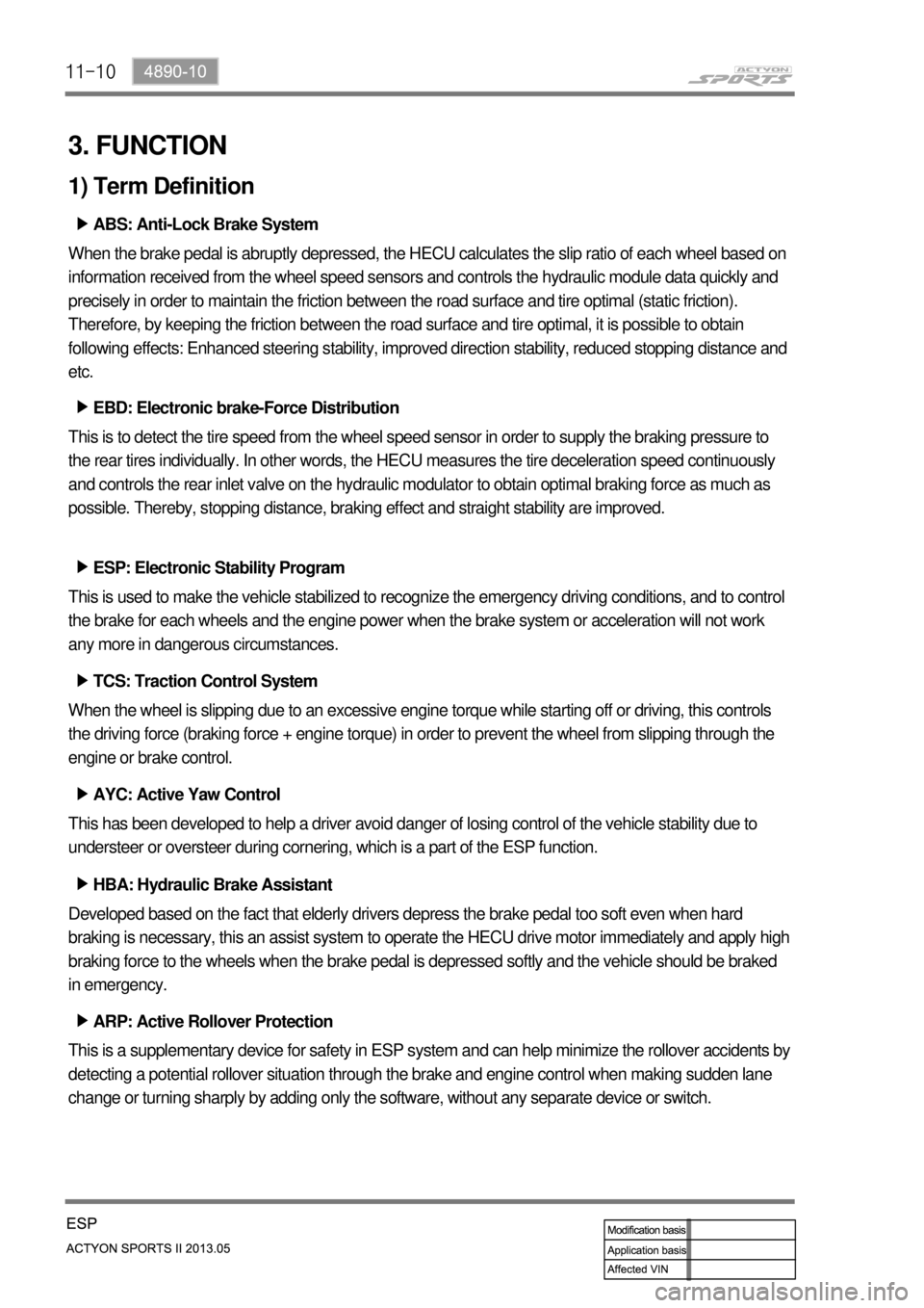
1) Term Definition
ABS: Anti-Lock Brake System ▶
When the brake pedal is abruptly depressed, the HECU calculates the slip ratio of each wheel based on
information received from the wheel speed sensors and controls the hydraulic module data quickly and
precisely in order to maintain the friction between the road surface and tire optimal (static friction).
Therefore, by keeping the friction between the road surface and tire optimal, it is possible to obtain
following effects: Enhanced steering stability, improved direction stability, reduced stopping distance and
etc.
EBD: Electronic brake-Force Distribution ▶
This is to detect the tire speed from the wheel speed sensor in order to supply the braking pressure to
the rear tires individually. In other words, the HECU measures the tire deceleration speed continuously
and controls the rear inlet valve on the hydraulic modulator to obtain optimal braking force as much as
possible. Thereby, stopping distance, braking effect and straight stability are improved.
ESP: Electronic Stability Program ▶
This is used to make the vehicle stabilized to recognize the emergency driving conditions, and to control
the brake for each wheels and the engine power when the brake system or acceleration will not work
any more in dangerous circumstances.
TCS: Traction Control System ▶
When the wheel is slipping due to an excessive engine torque while starting off or driving, this controls
the driving force (braking force + engine torque) in order to prevent the wheel from slipping through the
engine or brake control.
AYC: Active Yaw Control ▶
This has been developed to help a driver avoid danger of losing control of the vehicle stability due to
understeer or oversteer during cornering, which is a part of the ESP function.
HBA: Hydraulic Brake Assistant ▶
Developed based on the fact that elderly drivers depress the brake pedal too soft even when hard
braking is necessary, this an assist system to operate the HECU drive motor immediately and apply high
braking force to the wheels when the brake pedal is depressed softly and the vehicle should be braked
in emergency.
ARP: Active Rollover Protection ▶
This is a supplementary device for safety in ESP system and can help minimize the rollover accidents by
detecting a potential rollover situation through the brake and engine control when making sudden lane
change or turning sharply by adding only the software, without any separate device or switch.
Page 614 of 751

11-12
4. PRECAUTIONS
The warning lamp flashes and warning beep sounds when the ESP is operating
When the ESP operates during vehicle movement, the ESP warning lamp on the instrument panel
flashes and beep comes on every 0.1 second. The ESP system is only a supplementary device for
comfortable driving. When the vehicle exceeds its physical limits, it cannot be controlled.
Do not rely on the system. Keep on the safe driving.
Feeling when ESP is working
When the ESP system activates, the feeling can be different depending on vehicle driving
conditions.
For example, you will feel differently when the ESP system is activated during the ABS is operating
with the brakes applied and when the brakes are not applied on a curve.
If the ESP system operates when the brake is applied, the brake pressure will be increased on the
corresponding wheel which already has braking pressure for the ESP controls.
ARP Operation
During the ARP operation, vehicle safety (rollover prevention) takes the first priority and thus,
stronger engine control is in effect. Consequently, the vehicle speed decreases rapidly, so the driver
must take caution for the vehicle may drift away from the lane.
Noise and vibration that driver feels when ESP system is operating
The ESP system may transfer noise and vibration to the driver due to the pressure changes caused
by the motor and valve operations in a very short period of time. And, keep in mind that the output
and vehicle speed could be decreased without rpm increase due to the ASR function that controls
the engine power.
Page 621 of 751

11-194890-10
4) HBA (Hydraulic Brake Assist System)
(1) Purpose
HBA (Hydraulic Brake Assist) system helps in an emergency braking situation when the driver applies
the brake fast, but not with sufficient pressure, which leads to dangerously long braking distance. ECU
recognizes the attempt at full braking and transmits the signal calling for full brake pressure from the
hydraulic booster. An inexperienced, elderly or physically weak driver may suffer from the accident by not
fully pressing the brake pedal when hard braking is required under emergency. The HBA System
increases the braking force under urgent situations to enhance the inputted braking force from the driver.
Based on the fact that some drivers depress the brake pedal too soft even under when hard braking is
necessary, the HECU system is a safety supplementary system that builds high braking force during
initial braking according to pressure value of the brake pressure sensor and the pressure changes of the
pressure sensor intervals. When the system is designed to apply high braking force when brake pedal is
depressed softly by an elderly or physically weak driver, the vehicle will make abrupt stopping under
normal braking situation due to high braking pressure at each wheels.
(2) Operation
The brake pressure value and the changed value of the pressure sensor are the conditions in which the
HBA System operates. There are 2 pressure sensors under the master cylinder. When the ESP ECU
system determines that emergency braking is present, the pump operates, the brake fluid in the master
cylinder is sent to the pump and the braking pressure is delivered to the wheels via the inlet valves . If the
drive depress the brake pedal slowly, the pressure change is not high. In this case, only the conventional
brake system with booster is activated.
(3) Operating conditions
Sensor pressure: over 40 bar
Pressure changes: over 850 bar/sec
Vehicle speed: over 30 km/h -
-
-