Page 557 of 1336
1490-00
1. ENGINE DATA LIST
Data Unit Value
Coolant temperature
Intake air temperature(varies according to ambient air temperature or
engine mode)
Idle speed rpm
Engine load % 18~25%
Mass air flow kg/h 16~25kg/h
Throttle position angle
Engine torque Nm varies according to engine conditions
Injection time Ms -
Battery voltage V 13.5V~14.1V
Accelerator pedal position
1V 0.3~4.8 V
Accelerator pedal position
2V 0.3~2.4 V
Oxygen sensor mV 0~5 V
OCV (Oil Control Valve) % 0~100%
VIS solenoid valve 1=ON / 0=OFF -
A/C compressor switch
1=ON / 0=OFF-
Full load 1=ON / 0=OFF -
Knocking control 1=ON / 0=OFF -
Brake switch 1=ON / 0=OFF -
Cruise control 1=ON / 0=OFF -
Page 569 of 1336

0000-00
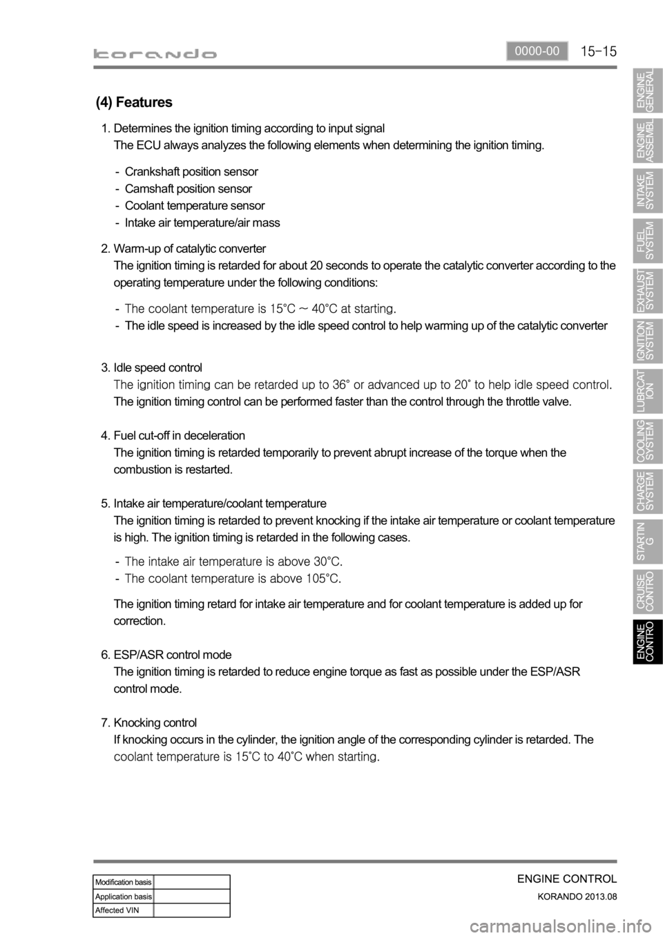
(4) Features
Determines the ignition timing according to input signal
The ECU always analyzes the following elements when determining the ignition timing. 1.
Crankshaft position sensor
Camshaft position sensor
Coolant temperature sensor
Intake air temperature/air mass -
-
-
-
Warm-up of catalytic converter
The ignition timing is retarded for about 20 seconds to operate the catalytic converter according to the
operating temperature under the following conditions: 2.
The idle speed is increased by the idle speed control to help warming up of the catalytic converter -
-
Idle speed control
The ignition timing control can be performed faster than the control through the throttle valve.
Fuel cut-off in deceleration
The ignition timing is retarded temporarily to prevent abrupt increase of the torque when the
combustion is restarted.
Intake air temperature/coolant temperature
The ignition timing is retarded to prevent knocking if the intake air temperature or coolant temperature
is high. The ignition timing is retarded in the following cases. 3.
4.
5.
-
-
The ignition timing retard for intake air temperature and for coolant temperature is added up for
correction.
ESP/ASR control mode
The ignition timing is retarded to reduce engine torque as fast as possible under the ESP/ASR
control mode.
Knocking control
If knocking occurs in the cylinder, the ignition angle of the corresponding cylinder is retarded. The
6.
7.
Page 571 of 1336

0000-00
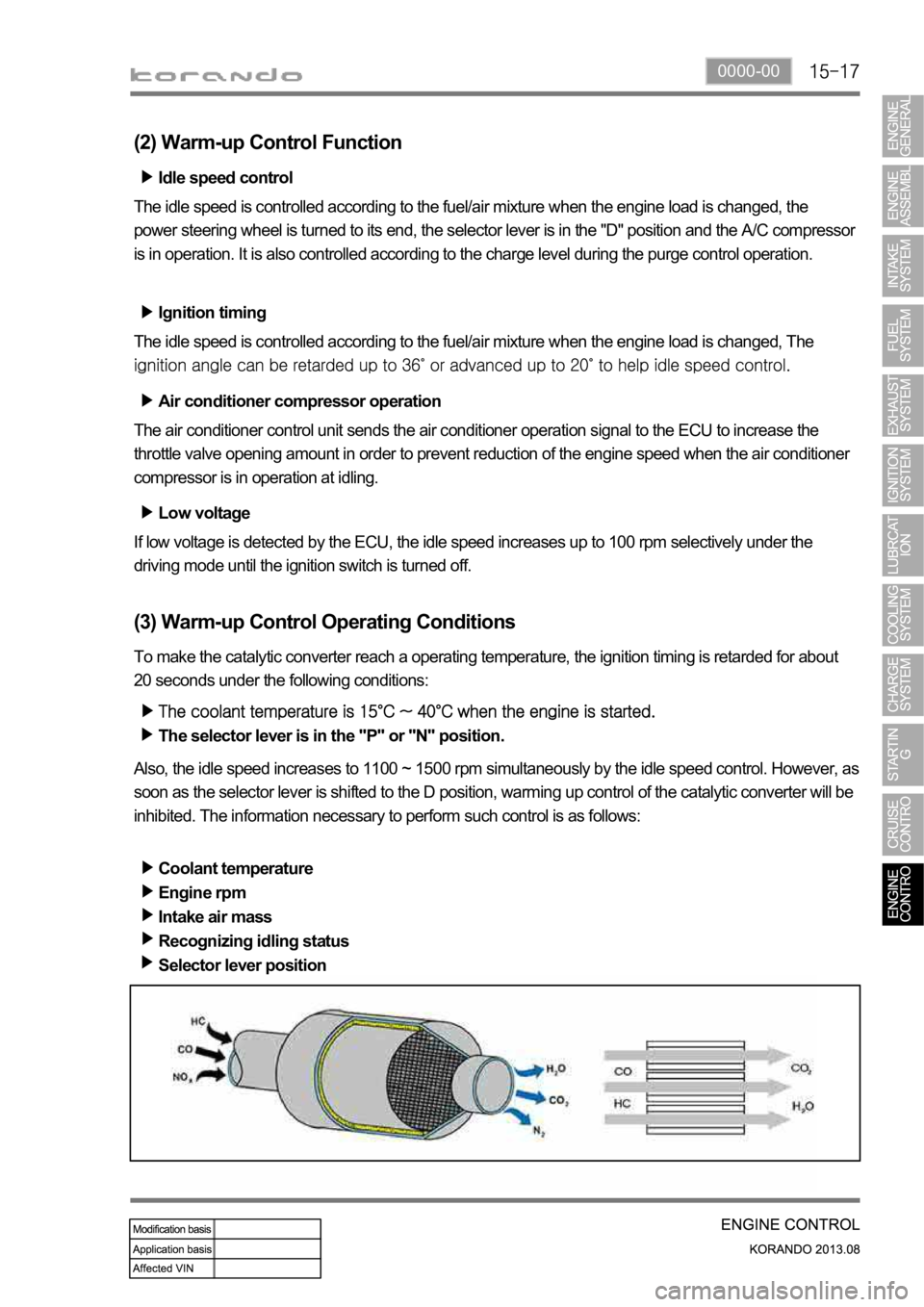
(2) Warm-up Control Function
Low voltage
If low voltage is detected by the ECU, the idle speed increases up to 100 rpm selectively under the
driving mode until the ignition switch is turned off. Idle speed control
The idle speed is controlled according to the fuel/air mixture when the engine load is changed, the
power steering wheel is turned to its end, the selector lever is in the "D" position and the A/C compresso
r
is in operation. It is also controlled according to the charge level during the purge control operation.
Ignition timing
The idle speed is controlled according to the fuel/air mixture when the engine load is changed, The
Air conditioner compressor operation
The air conditioner control unit sends the air conditioner operation signal to the ECU to increase the
throttle valve opening amount in order to prevent reduction of the engine speed when the air conditioner
compressor is in operation at idling.
(3) Warm-up Control Operating Conditions
To make the catalytic converter reach a operating temperature, the ignition timing is retarded for about
20 seconds under the following conditions:
The selector lever is in the "P" or "N" position.
Also, the idle speed increases to 1100 ~ 1500 rpm simultaneously by the idle speed control. However, as
soon as the selector lever is shifted to the D position, warming up control of the catalytic converter will be
inhibited. The information necessary to perform such control is as follows:
Coolant temperature
Engine rpm
Intake air mass
Recognizing idling status
Selector lever position
Page 572 of 1336
6) Cooling Fan Control
(1) Overview of Cooling Fan and A/C Compressor
The cooling system maintains the engine temperature at an efficient level during all engine operating
conditions. The water pump draws the coolant from the radiator. The coolant then circulates through
water jackets in the engine block, the intake manifold, and the cylinder head. When the coolant reaches
the operating temperature of the thermostat, the thermostat opens. The coolant then goes back to the
radiator where it cools. The heat from automatic transaxle is also cooled down through the radiator by
circulating the oil through the oil pump. There are two cooling fans (180W+120W) in G20DF engine. ECU
controls the electric cooling fans with three cooling fan relays to improve the engine torque and air
conditioning performance.
(2) Components
Refrigerant pressure
sensorCoolant temperature
sensorG20DF Engine
ECURelay box in engine
compartment
A/C compressorCooling fan moduleT-MAP sensor
Page 590 of 1336
0000-00
1. SPECIFICATIONS
System Unit Description Specification
Intake
systemAir cleaner elementFiltering type Dry, filter element
Filtering area
Service intervalEU: Change every 20,000 km
(But, shorten the service
interval under severe
conditions)
GEN: Clean every 7,500 km,
change every 15,000 km (But,
shorten the service interval
under severe conditions)
Air cleaner assemblyWeight 1.5kg
Operating temperature
Capacity 8L
IntercoolerCore material Aluminum
Size 510X122X67(WxHxT)
Tank materialPlastic (Molding)
Efficiency 80%
Exhaust
systemTurbocharger assemblyMax. temperature of turbine
housing
Diameter of turbine housing
Diameter of compressor
housing
Cooling type Air cooled type
Page 595 of 1336

Swirl control valve
It operates variably in accordance with the
engine load and rpm.
Intake manifold
It is the passage for intake air when the swirl
vale is operating. The T-MAP sensor for
measuring the pressure and temperature of
pressurized air in turbocharger is installed on
the left top of intake manifold.
3. LAYOUT OF INTAKE SYSTEM
1) Overview
The intake system for D20DTF(Low CO2) engine is equipped with a throttle body which includes a flap.
This flap is controlled by an electrical signal to cut off the intake air entering to the engine when the
ignition switch is turned off. The intake manifold contains the swirl control valve and dual port system to
make the optimum turbulence. The T-MAP sensor is located on the left top of the intake manifold and
the HFM sensor for precise control is located at the rear side of air cleaner. To reduce the intake noise
and to improve the intake efficiency, the volume of air cleaner has been increased.
2) Components
Electric throttle body
Page 1197 of 1336
6810-00
Intake sensor
It is mounted to the side of
evaporator core and detects the
temperature of the evaporator
core.Water temperature
sensor
It is mounted to the heater pipe
part and detects the coolant
temperature.
3) Air Conditioner Module Layout
Temp actuator
It changes the air mix door
opening according to the
control command from the
heater and A/C control
assembly.Evaporator core
It cools the surrounding air by
passing through the low-
temperature and low-pressure
refrigerant sprayed from the
expansion valve.
Heater core
It is mounted to the left-hand of
the air conditioner module and
heats the indoor using the heat
of the engine coolant.
Mode actuator
It controls the air outlet damper
to the five directions according
to the control command from
the heater and A/C control
assembly.
Page 1198 of 1336
Blower motor
It is mounted to the bottom of
the blower box and sends the
air inside of the vehicle. PTC heater
It is mounted to the heater air
outlet in the heater module
and warms the air from the
heater to the air vent.
Intake actuator
It changes the air source selection
mode according to the control
command from the heater and A/C
control assembly.A/C filter
It is mounted to the top of the
blower motor and filters the air
before it is discharged through
the duct.
MOS module
It controls the rotation speed of
the blower motor by receiving the
fan speed control signal from the
heater and A/C control assembly.