Page 1031 of 1336
3660-01
The shiftable gear can be adjusted by pressing the
"UP (D+)" or "DOWN(D-)" switch when the gear
Shift lock release button
If the selector lever cannot be moved from
while pushing down this button with finger. For
safety, turn off the engine and depress the
brake pedal before the attempt.Shift up Shift down Tip switches on steering wheel
Meter cluster
This indicator shows the current position of
the gear.
Gear selector lever
Lever positions
P : Park
R : reverse
N : Neutral
D : DriveTip switch (manual shift switch)
The shiftable gear can be adjusted by
moving this switch to forward and rearward
position.
Selection of Manual/Automatic Shift Function
D: Automatic shift according to the driving condition
M: Manual shift
Page 1042 of 1336

4. LIMP HOME MODE
When the transaxle is defective
In the event of a system fault, the TCU also provides for failure mode effect control (FMEC) to maintain
maximum functional operation of the transaxle. (There are 3 FMEC modes, mechanical limp-home
mode, electrical limp-home mode, limp-home mode C.)
In the event of a total loss of control or electrical power, the basic transaxle functions (Park, Reverse,
Neutral and Drive) are retained. The 4th and reverse gear ratios with the torque converter clutch in the
unlocked state are the retained gear states the hydraulic system supports without any electrical
assistance. (Mechanical limp-home)
If the speed sensor circuit is failed, the gear is fixed to 4th gear, but manual shifting
If the inhibitor switch signals are invalid, shifting to1st and 2nd gear is forbidden. (Limp-home C)
The TCU communicates with other vehicle electronic control modules by the controller area network
(CAN). If a major fault is developed, the transaxle may not accomplish the intelligent shift control. The
TCU controls the transaxle with preset values.
The TCU also provides for transaxle diagnostics, which meet the requirements of OBD II regulation,
monitoring all components which may effect vehicle emissions. 1.
2.
3.
4.
5.
6.
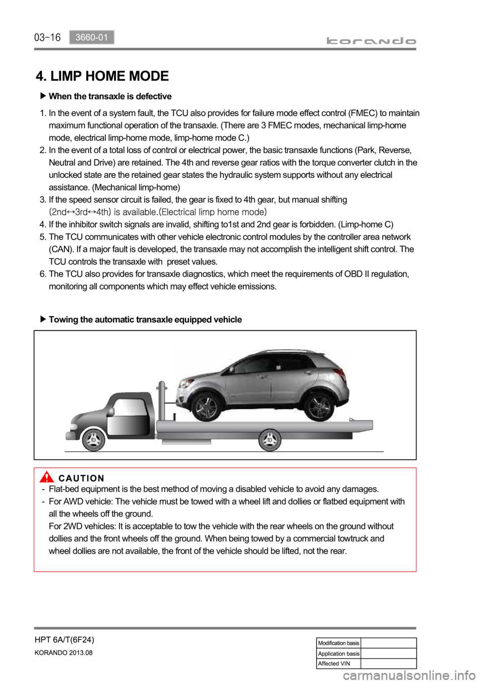
Towing the automatic transaxle equipped vehicle
Flat-bed equipment is the best method of moving a disabled vehicle to avoid any damages.
For AWD vehicle: The vehicle must be towed with a wheel lift and dollies or flatbed equipment with
all the wheels off the ground.
For 2WD vehicles: It is acceptable to tow the vehicle with the rear wheels on the ground without
dollies and the front wheels off the ground. When being towed by a commercial towtruck and
wheel dollies are not available, the front of the vehicle should be lifted, not the rear. -
-
Page 1064 of 1336
0000-00
1. SPECIFICATION
Description Specification
Operating type Hydraulic type
Clutch cover Type Diaphragm spring strap
Adjusting type SATIC (Self Adjusting Technology with
Integrated Cassette) type
Clutch pedal Type Suspended type
Max. operating travel
Pedal free play (Longitudinal)
Pedal free play (Transverse) 3 mm
Clutch disc Type Dry type single diaphragm (Rigid type)
Diameter of facing
Thickness of disc
Numbers of disc 2
Weight 1.18 kg
Flywheel type DMF (Dual Mass Flywheel)
Setting load of clutch cover assembly At least 7,800 N
Clutch master cylinder Operating travel 30 mm
Inner diameter 17.46 mm
Concentric slave
cylinderMaximum operating travel 12.55 mm
Operating pressure Maximum 50 bar
Standard DOT 3 or DOT 4
Capacity As required
Clutch oil
Page 1066 of 1336
0000-00
1. OVERVIEW
The hydraulic clutch transmits the force required to operate the clutch pedal to the concentric slave
cylinder fitted to the clutch housing as a hydraulic pressure.
(The hydraulic pressure is transmitted in the following order: Clutch pedal - Clutch master cylinder -
Clutch pipe - Clutch damper - Clutch pipe and hose - Concentric slave cylinder - Pressure plate -
Flywheel.)
If a driver depress the clutch pedal, the hydraulic pressure is generated in the master cylinder. It is
transmitted to the concentric slave cylinder through the pipe, resulting in the cylinder being forced out. At
this time, the clutch disc is forced against the cylinder by pushing the cover. This, in turn, remove the
flywheel from the pressure plate. As a consequence, the power from the engine will be cut off and the
gear change can be carried out.
Page 1068 of 1336

0000-00
Operating Elements
The clutch "release" system consists of the clutch pedal and clutch release cylinder.
This system directly releases the clutch by using hydraulic pressure while the conventional clutch system
releases the clutch by using release lever and release fork. This system provides higher efficiency than
conventional clutch system, and its durability is superior.
Clutch master cylinder (mounted on clutch pedal)
Concentric slave cylinder pipe (mounted inside of transmission) -
-Driving elements
The driving elements consist of two flat surfaces machined to a smooth finish.
One of these is the rear face of the engine flywheel and the other is the clutch pressure plate. The clutch
pressure plate is fitted into a clutch steel cover, which is bolted to the flywheel.
Driven elements
The driven element is the clutch disc with a splined hub which is free to slide lengthwise along the splines
of the input shaft.
The driving and driven elements are held in contact by spring pressure. This pressure is exerted by a
diaphragm spring in the clutch cover pressure plate assembly.
2) Overview
Page 1069 of 1336
3) Layout
Clutch discClutch cover assembly
Concentric slave cylinderDual mass flywheel (DMF)
Clutch setting jig
Page 1070 of 1336
0000-00
3. DUAL MASS FLYWHEEL (DMF)
The dual mass flywheel (DMF) is of having a mass divided into two halves.
While one mass is connected to the engine crankshaft, which is affected by the mass moment of inertia
of the engine, the other mass is affected by one of the transmission.
The divided dual masses are connected to the coil spring and damping system internally.
The DMF has the following benefits:
Reducing fuel consumption by lowering engine speed
Reducing rattling noise and vehicle vibration in all driving ranges
Reducing synchronization wear
Facilitating gear change
Protecting power train parts by preventing excessive load from being delivered -
-
-
-
-
Primary flywheel
Secondary flywheel
Arc damper spring
Torque limiter
Ring gear 1.
2.
3.
4.
5.
Page 1076 of 1336

4110-01
2. TORQUE STEER
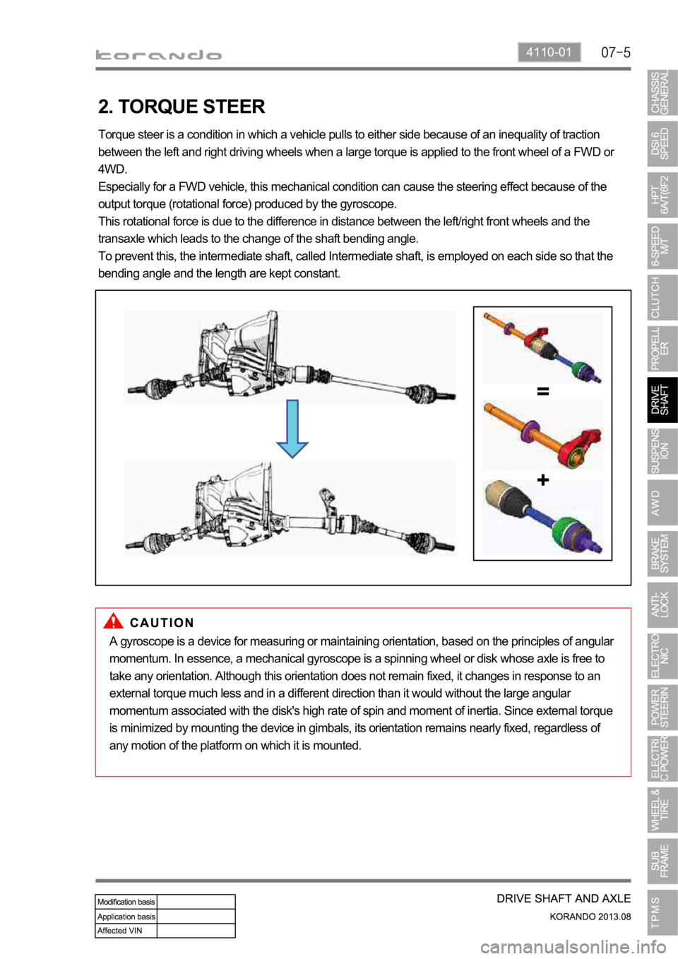
Torque steer is a condition in which a vehicle pulls to either side because of an inequality of traction
between the left and right driving wheels when a large torque is applied to the front wheel of a FWD or
4WD.
Especially for a FWD vehicle, this mechanical condition can cause the steering effect because of the
output torque (rotational force) produced by the gyroscope.
This rotational force is due to the difference in distance between the left/right front wheels and the
transaxle which leads to the change of the shaft bending angle.
To prevent this, the intermediate shaft, called Intermediate shaft, is employed on each side so that the
bending angle and the length are kept constant.
A gyroscope is a device for measuring or maintaining orientation, based on the principles of angular
momentum. In essence, a mechanical gyroscope is a spinning wheel or disk whose axle is free to
take any orientation. Although this orientation does not remain fixed, it changes in response to an
external torque much less and in a different direction than it would without the large angular
momentum associated with the disk's high rate of spin and moment of inertia. Since external torque
is minimized by mounting the device in gimbals, its orientation remains nearly fixed, regardless of
any motion of the platform on which it is mounted.