Page 854 of 1336
8510-00
Heater and A/C control switch
Automatic Manual
1) Overview
3. INTEGRATED INSTRUMENT PANEL SWITCH
It is mounted to the instrument panel and combined with the cooler; which provides cooling and
dehumidification by repeating the cycles of compression -> condensation -> expansion -> evaporation,
and heater; which controls the heating systemically in the course of circulating the coolant heated by the
engine heat to the heater. This allows the driver to maintain the indoor comfortable conditions throughout
the year.
Temperature control
dial
AUTO switch
LCD display
Fan speed dial
A/C switch A.
B.
C.
D.
E.ON/OFF switch
Defroster mode switch
Indoor temperature sensing
part
Air source selection switch
Air distribution switch F.
G.
H.
I.
J.Fan speed dial
A/C switch
MAX A/C switch
Defroster mode switch
Defroster & foot mode
switch
Temperature control dial A.
B.
C.
D.
E.
F.Air source selection switch
Vent mode switch
Bi-level mode switch
Foot mode switch G.
H.
I.
J.
Page 1014 of 1336

5. TRANSAXLE ELECTRONIC CONTROL SYSTEM
1) General Information
The transmission control unit (TCU) and its input/output network control the following transmission
operations:
Shift timing
Line pressure
Clutch pressure (shift feel)
Torque converter clutch -
-
-
-
also uses these signals when determining transaxle operating strategy. Using all of these input signals,
the TCU can determine when the time and conditions are right for a shift, or when to apply or release the
torque converter clutch. It will also determine the pressure needed to optimise shift feel. To accomplish
this, the TCU operates six variable bleed control solenoids and four on/off solenoids to control transaxle
operation.
2) TCU (Transmission Control Unit)
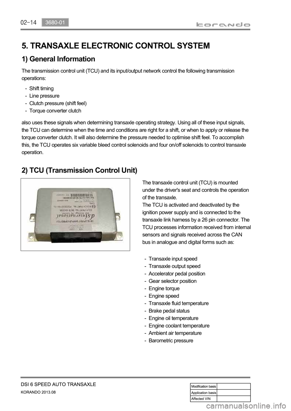
The transaxle control unit (TCU) is mounted
under the driver's seat and controls the operation
of the transaxle.
The TCU is activated and deactivated by the
ignition power supply and is connected to the
transaxle link harness by a 26 pin connector. The
TCU processes information received from internal
sensors and signals received across the CAN
bus in analogue and digital forms such as:
Transaxle input speed
Transaxle output speed
Accelerator pedal position
Gear selector position
Engine torque
Engine speed
Transaxle fluid temperature
Brake pedal status
Engine oil temperature
Engine coolant temperature
Ambient air temperature
Barometric pressure -
-
-
-
-
-
-
-
-
-
-
-
Page 1043 of 1336

3660-01
5. TRANSAXLE ELECTRONIC CONTROL SYSTEM
1) General Information
The transmission control unit (TCU) and its input/output network control the following transmission
operations:
Shift timing
Line pressure
Clutch pressure (shift feel)
Torque converter clutch -
-
-
-
also uses these signals when determining transaxle operating strategy. Using all of these input signals,
the TCU can determine when the time and conditions are right for a shift, or when to apply or release the
torque converter clutch. It will also determine the pressure needed to optimise shift feel.
2) TCU (Transmission Control Unit)
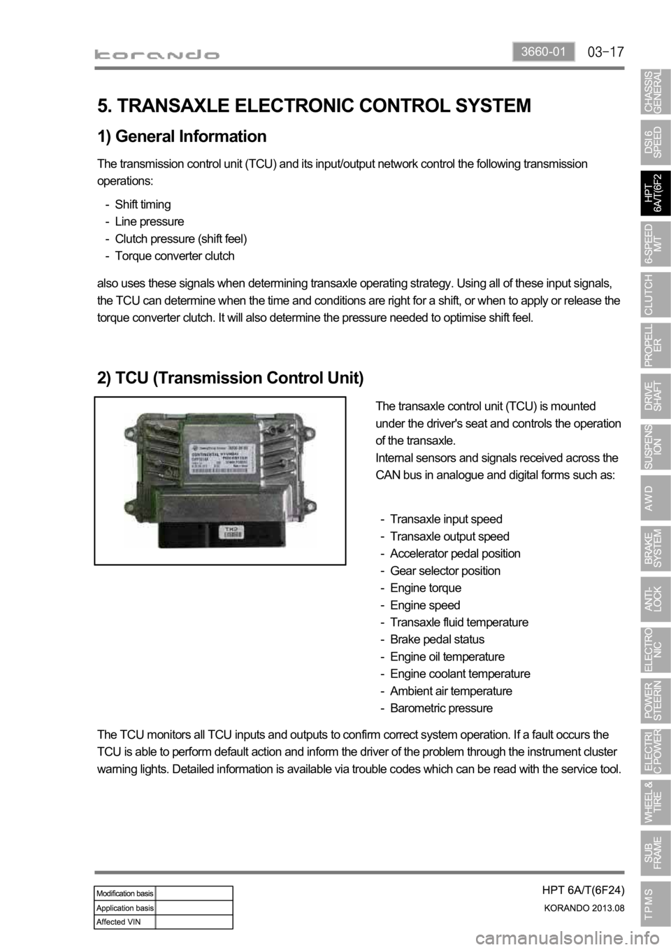
The transaxle control unit (TCU) is mounted
under the driver's seat and controls the operation
of the transaxle.
Internal sensors and signals received across the
CAN bus in analogue and digital forms such as:
Transaxle input speed
Transaxle output speed
Accelerator pedal position
Gear selector position
Engine torque
Engine speed
Transaxle fluid temperature
Brake pedal status
Engine oil temperature
Engine coolant temperature
Ambient air temperature
Barometric pressure -
-
-
-
-
-
-
-
-
-
-
-
The TCU monitors all TCU inputs and outputs to confirm correct system operation. If a fault occurs the
TCU is able to perform default action and inform the driver of the problem through the instrument cluster
warning lights. Detailed information is available via trouble codes which can be read with the service tool.
Page 1194 of 1336
2. LAYOUT
1) Exterior Layout
Liquid and suction pipe
The high/low-pressure A/C refrigerant flows
through this pipe. It is fitted with the refrigerant
pressure sensor.
Electric fan
It cools down the A/C condenser to speed up the
compression for the refrigerant in the condenser.
Refrigerant pressure sensor
It is mounted to the latter part of the right
headlamp. It converts the A/C refrigerant pressure
to voltage value and sends it to the engine ECU.
A/C compressor
It is installed to the left side of the engine
assembly, compresses the low-temperature and
low-pressure coolant and converts it to the high-
temperature and high-pressure coolant. Then, it
sends the coolant to the A/C condenser.
Page 1197 of 1336
6810-00
Intake sensor
It is mounted to the side of
evaporator core and detects the
temperature of the evaporator
core.Water temperature
sensor
It is mounted to the heater pipe
part and detects the coolant
temperature.
3) Air Conditioner Module Layout
Temp actuator
It changes the air mix door
opening according to the
control command from the
heater and A/C control
assembly.Evaporator core
It cools the surrounding air by
passing through the low-
temperature and low-pressure
refrigerant sprayed from the
expansion valve.
Heater core
It is mounted to the left-hand of
the air conditioner module and
heats the indoor using the heat
of the engine coolant.
Mode actuator
It controls the air outlet damper
to the five directions according
to the control command from
the heater and A/C control
assembly.
Page 1202 of 1336

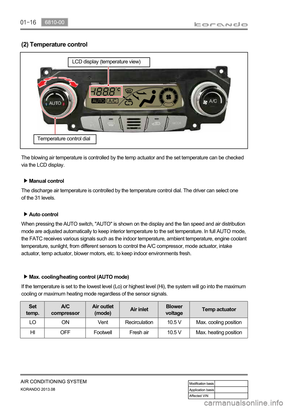
(2) Temperature control
The blowing air temperature is controlled by the temp actuator and the set temperature can be checked
via the LCD display.
Manual control
The discharge air temperature is controlled by the temperature control dial. The driver can select one
of the 31 levels.
Auto control
When pressing the AUTO switch, "AUTO" is shown on the display and the fan speed and air distribution
mode are adjusted automatically to keep interior temperature to the set temperature. In full AUTO mode,
the FATC receives various signals such as the indoor temperature, ambient temperature, engine coolant
temperature, sunlight, from different sensors to control the A/C compressor, mode actuator, intake
actuator, temp actuator, blower motors, etc. to keep indoor environments fresh.
Max. cooling/heating control (AUTO mode)
If the temperature is set to the lowest level (Lo) or highest level (Hi), the system will go into the maximum
cooling or maximum heating mode regardless of the sensor signals.
Set
temp.A/C
compressorAir outlet
(mode)Air inletBlower
voltageTemp actuator
LO ON Vent Recirculation 10.5 V Max. cooling position
HI OFF Footwell Fresh air 10.5 V Max. heating position
Temperature control dial
LCD display (temperature view)
Page 1204 of 1336
Initial fan speed control for cooling/heating
Cooling start control
by the air flow from the vent. Therefore, at the initial operation stage, the hot air is discharged to the
windshield (DEF mode) for about 5 seconds. -
Heating start control
When the engine coolant temperature is low or the wind temperature is not warmed up sufficiently,
the driver might feel uncomfortable by the air flow from the vent. Therefore, the fan speed is set to the
1st stage and the cool air is sent to the windshield until the coolant temperature increases to the
proper level (DEF mode). As the engine coolant temperature goes up, the mode is changed to
Defrost & Foot mode or AUTO mode to increase the speed of blower motor. This control is cancelled
control time must not exceed 10 minutes. -
Page 1221 of 1336

6810-00
5. PTC HEATER OPERATION PROCESS
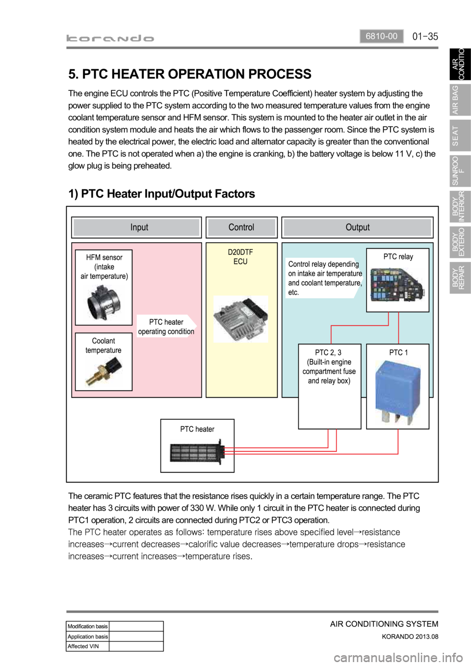
1) PTC Heater Input/Output Factors
The engine ECU controls the PTC (Positive Temperature Coefficient) heater system by adjusting the
power supplied to the PTC system according to the two measured temperature values from the engine
coolant temperature sensor and HFM sensor. This system is mounted to the heater air outlet in the air
condition system module and heats the air which flows to the passenger room. Since the PTC system is
heated by the electrical power, the electric load and alternator capacity is greater than the conventional
one. The PTC is not operated when a) the engine is cranking, b) the battery voltage is below 11 V, c) the
glow plug is being preheated.
The ceramic PTC features that the resistance rises quickly in a certain temperature range. The PTC
heater has 3 circuits with power of 330 W. While only 1 circuit in the PTC heater is connected during
PTC1 operation, 2 circuits are connected during PTC2 or PTC3 operation.