Page 856 of 1336

8510-00
Bi-level mode
switch
If the switch is
pressed, the indicator
comes on while the
air flows to the
footwell and the
upper part of the
body.Foot mode
switch
If the switch is
pressed, the indicator
comes on while the air
flows to the footwell
and the upper part of
the body.
Manual b.
Fan speed dial
Turn the dial to the left
or right to adjust the fan
speed in 7 steps. At this
time, the indicator lamp
comes on.
Vent mode switch
If the switch is
pressed, the
indicator comes on
while the air flows
to the upper part of
the body.Air source selection
switch
When the switch is pressed,
the indicator comes on and
the mode is switched to the
recirculation mode at the
same time. When pressed
again, the indicator goes out
and switched to the fresh air
mode at the same time.
MAX A/C switch
This is designed for increasing driver
comfort. When the switch is pressed, the
indicator comes on and the air
conditioner starts at the same time and
vent and recirculation modes are
selected automatically.Defroster & foot
mode switch
If the switch is pressed, the
indicator comes on while the
air flows to the footwell and
the windshield.
Defroster mode switch
This is used to remove the
condensation from the windshield.
When you press the switch, the
indicator comes on and the air
distribution is changed to the
windshield at the same time, then
the air conditioner starts to operate.A/C switch
When the switch is
pressed, the indicator
comes on and the air
conditioner starts at the
same time. Pressing the
switch again gets the
indicator lamp go off and
the air conditioner stop at
the same time.Temperature control
dial
Turn the dial to the left
or right to adjust the set
temperature.
Page 1000 of 1336

4) Basic Inspection
(1) Horn operation
Listen for the horn sound when pressing the horn pad on the steering wheel. -
(2) Brake operation
Check if there is any abnormal noise, unusually long braking distance, or uneven braking force. If the
brake warning lamp does not go out even after starting the engien or are flashing during driving,
have the brake system checked immediately.
Check the brake pipes and hoses for connection, oil leak, crack or interference after changing the
position of tires. When replacing the tires, check the brake disc for surface condition and wear.
Check the parking brake cable and brake operation. Shorten the checking interval if the parking
brake is used frequently. -
-
-
(3) Exhaust system
Be aware to any changes in sound or smell from the exhaust system. These may be caused by leak or
overheat. Have the exhaust system checked and repaired immediately.
Inspect the exhaust system including catalytic converter. Inspect all the components and body frame
near the exhaust system. -
-
(4) Tires
Unusual vibration of the steering wheel and seats or pulling to one side on the straight and level roads
may indicates the uneven tire inflation pressure or poor wheel balance. -
(5) Steering and suspension system
Inspect the front and rear suspension and the steering system for damage, looseness or missing
parts, signs of wear or lack of lubrication. Inspect the power steering line and the hoses for
connection, leak, crack and chafing. Inspect the drive axle boot and seals for damage, tear or leak.
Replace or repair the system if necessary. -
(6) Engine oil
Check the oil level when the engine is still warm and add the specified engine oil if necessary. -
(7) Coolant
Check the coolant level in the coolant reservoir, coolant conditions (contamination, foreign material),
and hoses for damage and leak. Replace or add the Ssangyong genuine coolant, if needed. -
(8) Engine drive belt
Check all drive belts on the engine for wear, crack and looseness. Retighten or replace the belt, if
needed. -
Page 1014 of 1336

5. TRANSAXLE ELECTRONIC CONTROL SYSTEM
1) General Information
The transmission control unit (TCU) and its input/output network control the following transmission
operations:
Shift timing
Line pressure
Clutch pressure (shift feel)
Torque converter clutch -
-
-
-
also uses these signals when determining transaxle operating strategy. Using all of these input signals,
the TCU can determine when the time and conditions are right for a shift, or when to apply or release the
torque converter clutch. It will also determine the pressure needed to optimise shift feel. To accomplish
this, the TCU operates six variable bleed control solenoids and four on/off solenoids to control transaxle
operation.
2) TCU (Transmission Control Unit)
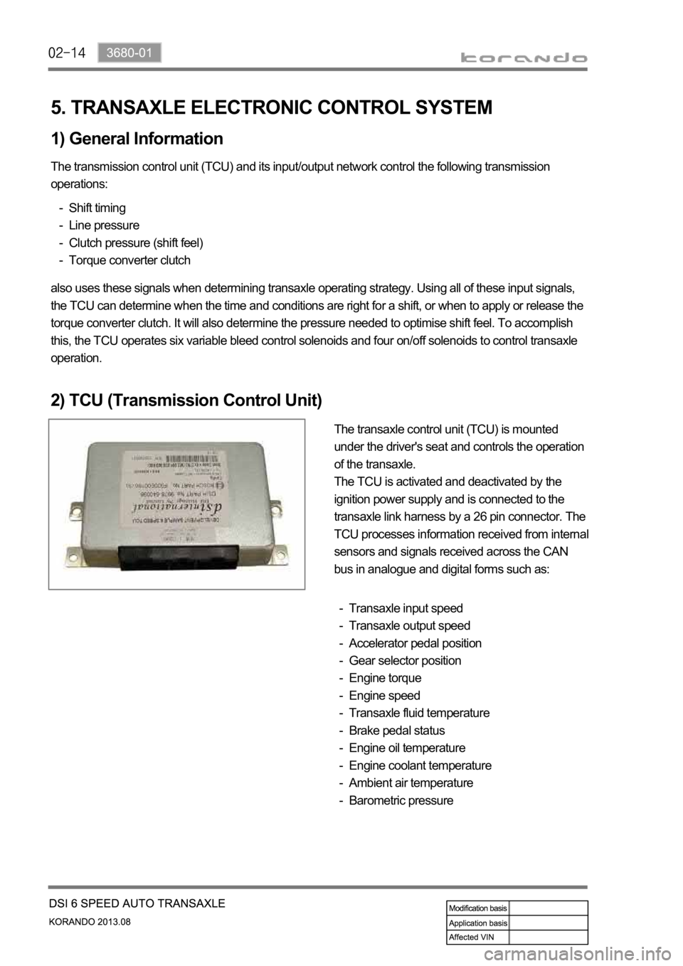
The transaxle control unit (TCU) is mounted
under the driver's seat and controls the operation
of the transaxle.
The TCU is activated and deactivated by the
ignition power supply and is connected to the
transaxle link harness by a 26 pin connector. The
TCU processes information received from internal
sensors and signals received across the CAN
bus in analogue and digital forms such as:
Transaxle input speed
Transaxle output speed
Accelerator pedal position
Gear selector position
Engine torque
Engine speed
Transaxle fluid temperature
Brake pedal status
Engine oil temperature
Engine coolant temperature
Ambient air temperature
Barometric pressure -
-
-
-
-
-
-
-
-
-
-
-
Page 1043 of 1336

3660-01
5. TRANSAXLE ELECTRONIC CONTROL SYSTEM
1) General Information
The transmission control unit (TCU) and its input/output network control the following transmission
operations:
Shift timing
Line pressure
Clutch pressure (shift feel)
Torque converter clutch -
-
-
-
also uses these signals when determining transaxle operating strategy. Using all of these input signals,
the TCU can determine when the time and conditions are right for a shift, or when to apply or release the
torque converter clutch. It will also determine the pressure needed to optimise shift feel.
2) TCU (Transmission Control Unit)
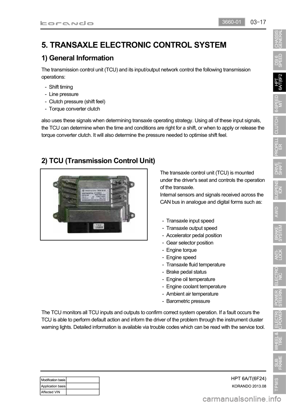
The transaxle control unit (TCU) is mounted
under the driver's seat and controls the operation
of the transaxle.
Internal sensors and signals received across the
CAN bus in analogue and digital forms such as:
Transaxle input speed
Transaxle output speed
Accelerator pedal position
Gear selector position
Engine torque
Engine speed
Transaxle fluid temperature
Brake pedal status
Engine oil temperature
Engine coolant temperature
Ambient air temperature
Barometric pressure -
-
-
-
-
-
-
-
-
-
-
-
The TCU monitors all TCU inputs and outputs to confirm correct system operation. If a fault occurs the
TCU is able to perform default action and inform the driver of the problem through the instrument cluster
warning lights. Detailed information is available via trouble codes which can be read with the service tool.
Page 1185 of 1336

7. TIRE INFLATION PROCEDURE FOR VEHICLE WITH TPMS
1) Overview
For the vehicle with TPMS, the tire should be inflated in a method different from the conventional method
since the tire pressure values displayed on the tire pressure gauge and instrument cluster are different
after inflation.
The tire pressure displayed on the instrument cluster should be checked after a certain time delay
(wireless transmission time for wheel module).
The displayed value can be changed after driving even if it was set to the specified value.
2) Tire Inflation Procedure
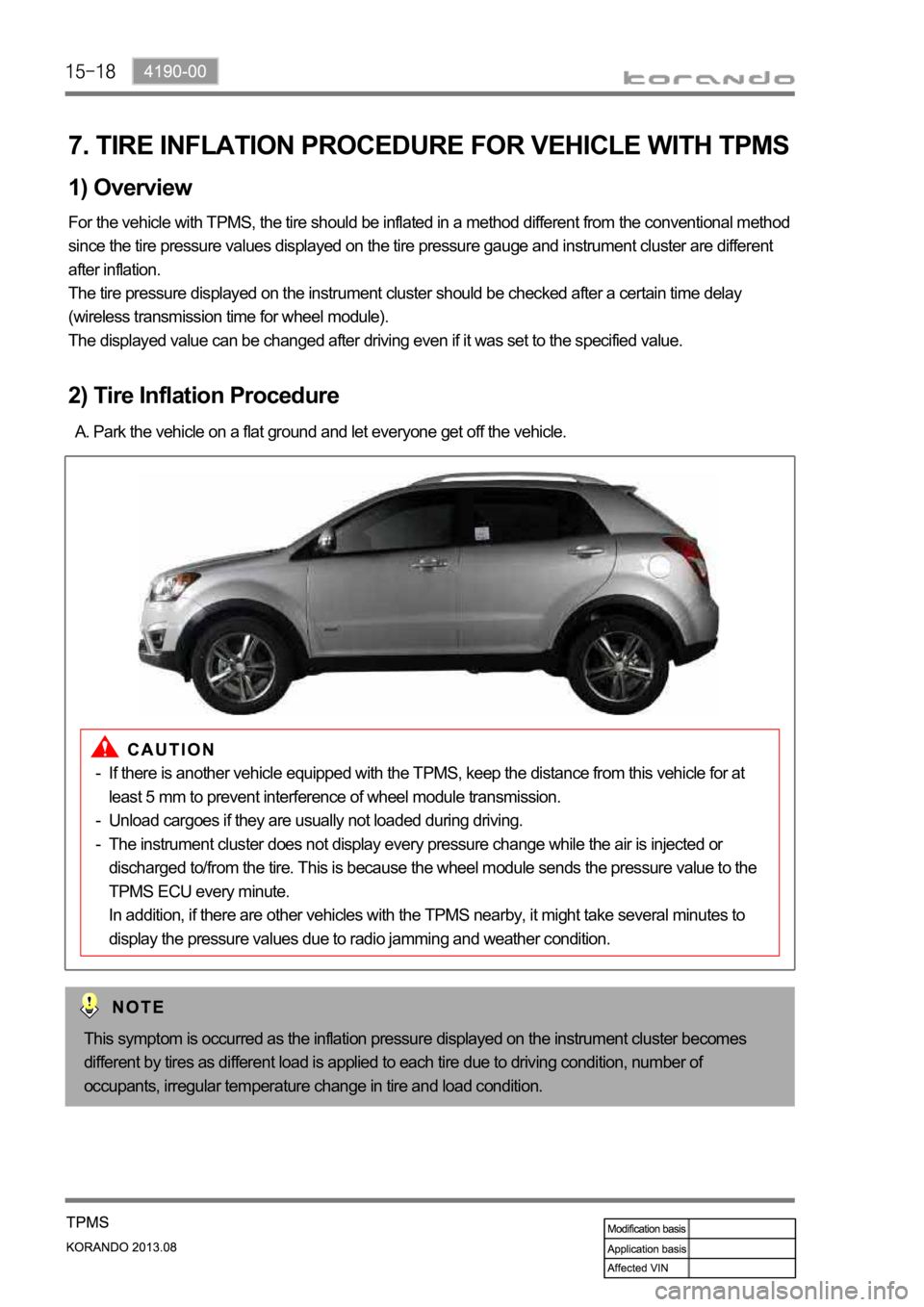
Park the vehicle on a flat ground and let everyone get off the vehicle. A.
This symptom is occurred as the inflation pressure displayed on the instrument cluster becomes
different by tires as different load is applied to each tire due to driving condition, number of
occupants, irregular temperature change in tire and load condition.
If there is another vehicle equipped with the TPMS, keep the distance from this vehicle for at
least 5 mm to prevent interference of wheel module transmission.
Unload cargoes if they are usually not loaded during driving.
The instrument cluster does not display every pressure change while the air is injected or
discharged to/from the tire. This is because the wheel module sends the pressure value to the
TPMS ECU every minute.
In addition, if there are other vehicles with the TPMS nearby, it might take several minutes to
display the pressure values due to radio jamming and weather condition. -
-
-
Page 1191 of 1336
6810-00
Heater & A/C control assembly
Heater and A/C control assembly design and switch arrangement changed
- Digital display (LCD display) with FATC used
- Push button type switch used (self-return type)
2. MAJOR CHANGES
Change of air conditioner pipe
With MTC
With FATC
With MTC
With FATC
Changes in heater and control assembly
Liquid and suction pipe
Liquid and suction pipe route changed due to change of headlamp mounting bracket
Page 1192 of 1336
1. OVERVIEW
The climate system in the vehicle is an air regulating system which keeps the indoor air pleasant through
the heating, ventilation and air conditioning systems. The air conditioning systems fall in to two
categories; FATC (Full Automatic Temperature Control), which is a temperature control device which
receives signals from various sensors (ambient temperature sensor, water temperature sensor, sun-
load sensor, AMP sensor) and control switches to control the blower motor and all kinds of actuator
(mode door actuator, mix door actuator, air source door actuator) through MICOM in the FATC,
therefore, the interior temperature of the vehicle is kept to the temperature which is set by a driver and
MTC (Manual Temperature Control), which controls all the actuator and blower motor by the driver.
Page 1196 of 1336
2) Interior Layout
Sun load sensor
It is mounted to the upper left-
hand of the instrument panel and
detects the sun-load enters to the
interior through the windshield
with a photo diode. Incar sensor
It is mounted to the rear of the
heater and A/C control panel
(with FATC) and detects the
interior air temperature drawn
through the senor inlet.Air conditioner module
It is mounted to inside of the
instrument panel and has the
evaporator core, heater core,
PTC heater and corresponding
actuator and different sensors.
Heater & A/C control assembly
With FATC With MTC
It falls in to two categories; FATC (Full Automatic Temperature Control) and MTC (Manual Temperature
Control), which controls the air conditioning system's operation.