2013 SSANGYONG KORANDO automatic transmission
[x] Cancel search: automatic transmissionPage 426 of 1336

0000-00
3) General Instructions
Before lifting up the vehicle with a lift, correctly support the lifting points.
When using a jack, park the vehicle on a level ground and place the wheel chocks under the tires.
Position the jack under the frame and lift up the vehicle and then support with chassis stand before
service work.
Make sure to disconnect the negative (-) cable from the battery to prevent any damage to electric
systems.
If you have to work on vehicle, cover the seats and floor with protection covers to avoid any
damage and contamination.
Brake fluid and anti-freeze can damage the painted surface of body. So carefully handle them
during service work.
To improve the efficiency of service work, use only recommended and specified tools.
Use only Ssangyong genuine spare parts.
Never reuse the cotter pin, gasket, O-ring, oil seal, lock washer and self-locking nut. Replace them
with new ones. If reused, normal functions cannot be maintained.
Store the disassembled parts as a set based on disassembly order and unit.
Pay particular attention not to miss or mix the fasteners.
If necessary, especially for inspection, clean the removed parts completely.
Apply the oil or grease on the running and sliding surfeces before installation. Use the specified
sealant and gasket to prevent leakage if necessary.
Tighten the fasteners to the specified tightening torque.
As a final stage of service work, check if the serviced system is working properly and the problem
has been eliminated clearly. (1)
(2)
(3)
(4)
(5)
(6)
(7)
(8)
(9)
(10)
(11)
(12)
(13)
(14) Remove the engine and transaxle as a set.
Manual transaxle: Transaxle can be separated after removing the front module (sub frame, engine
and transaxle).
Automatic transaxle: Transaxle can be separated after removing the sub frame. -
-
2) Equipment
Korando is FF (Front Engine Front Drive) type vehicle, and engine and powertrain system are
integrated into a module. Therefore, 2-post lift and general equipment are necessary when working
on the engine and transmission.
Major equipment: Engine and transmission jack, Engine stand, Engine crane, Transmission jack,
Engine hanger -
-
Page 782 of 1336

Ignition status change*
If above conditions are met again, the SKM re-verifies the transponder and sends the verification
status for another 10 sec.
When the ignition status is changed by a smart key verification while the transponder verification is
processed, the SKM sends the signal for [transponder verification fail], and sends the smart key
verification status for 10 sec. -
-
(6) Transmission position warning
When the gear selector lever is in a position other than P or N with IGN ON and engine started, the
SKM sends the [gear position warning] signal to the instrument cluster through the BCAN for up to 10
sec. until the operating conditions are deactivated.
Transmission position warning deactivation
When re-attempting to start with IGN1 ON and transmission in P or N -
(7) ESCL JAM warning
The SKM transmits the warning active command to the BCAN through the BCAN signals such as ESCL
NOT LOCKED warning signal or ESCL JAM warning signal within 10 seconds or until the active
command deactivation conditions will be met, if jam is occurred when the electric steering motor is
locked/unlocked.
Failure Detecting Conditions
When the UNLOCK retry occurs after ESCL LOCK command, the ESCL LOCK is performed.
- The UNLOCK retry is possible up to 2 times automatically. If the UNLOCK retry occurs 3 times
in succession, the ESCL NOT LOCKED warning is triggered.
- Reactivates when the ESCL LOCK conditions are met.
When the LOCK retry occurs after ESCL LOCK command, the command will be overridden without
retry.
- After the command is overridden, the ESCL NOT LOCKED warning is triggered.
- Reactivates when the LOCK conditions are met by pressing the START/STOP switch after
ESCL UNLOCK.
When the LOCK retry occurs after ESCL UNLOCK command, the ESCL UNLOCK is performed.
- The LOCK retry is possible up to 2 times automatically. If the LOCK retry occurs 3 times in
succession, the ESCL JAM warning is triggered.
- Reactivates when the ESCL UNLOCK conditions are met by pressing the START/STOP
switch.
When the UNLOCK retry occurs after ESCL UNLOCK command, the command will be overridden
without retry.
- After the command is overridden, the ESCL JAM warning is triggered.
- Reactivates when the UNLOCK conditions are met by pressing the START/STOP switch after
ESCL LOCK. 1.
2.
3.
4.
Page 876 of 1336

8510-00
3) Cruise Control Switch
Cruise control switch
The cruise control is an automatic speed control system that maintains a desired driving speed without
using the accelerator pedal. The cruise control switch is fitted to the bottom right section of the steering
wheel. When this switch is operated, the AUTO CRUISE or ECO lamp on the instrument cluster comes
on.
The cruise control switch has a fivefold switch in it. The engine ECU can determine the current driving
condition since the resistance varies depending on the operation of the switch.
The cruise control system is operated at vehicle speed of between 38 km/h and 150 km/h. The manual
transmission is operated in the range of 3rd gear or higher.
This function can be used at the following traffic condition. (It is important to be careful for using this
function)
Cruise control (ON)
Cruise control (OFF)
Cruise control (Acceleration)Cruise control (Deceleration)
Cruise control (Reset)
Page 986 of 1336

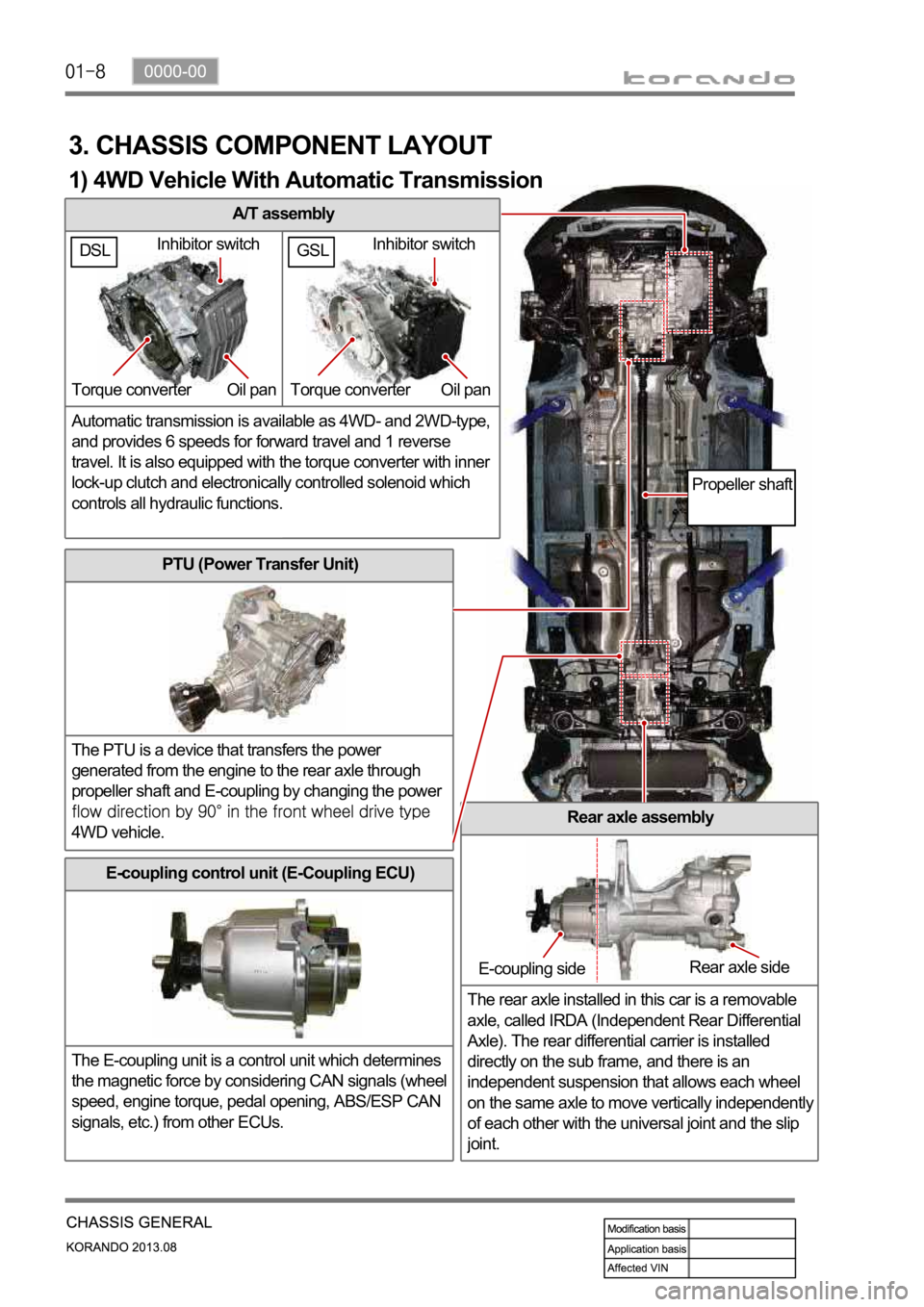
A/T assembly
Automatic transmission is available as 4WD- and 2WD-type,
and provides 6 speeds for forward travel and 1 reverse
travel. It is also equipped with the torque converter with inner
lock-up clutch and electronically controlled solenoid which
controls all hydraulic functions.
3. CHASSIS COMPONENT LAYOUT
PTU (Power Transfer Unit)
The PTU is a device that transfers the power
generated from the engine to the rear axle through
propeller shaft and E-coupling by changing the power
4WD vehicle.Rear axle assembly
The rear axle installed in this car is a removable
axle, called IRDA (Independent Rear Differential
Axle). The rear differential carrier is installed
directly on the sub frame, and there is an
independent suspension that allows each wheel
on the same axle to move vertically independentl
y
of each other with the universal joint and the slip
joint.
E-coupling control unit (E-Coupling ECU)
The E-coupling unit is a control unit which determines
the magnetic force by considering CAN signals (wheel
speed, engine torque, pedal opening, ABS/ESP CAN
signals, etc.) from other ECUs.
Inhibitor switch
Torque converter Oil pan
E-coupling sideRear axle side
Propeller shaft
1) 4WD Vehicle With Automatic Transmission
GSLDSLInhibitor switch
Torque converter Oil pan
Page 999 of 1336

0000-00
3) General Instructions
Before lifting up the vehicle with a lift, correctly support the lifting points.
When using a jack, park the vehicle on a level ground and place the wheel chocks under the tires.
Position the jack under the frame and lift up the vehicle and then support with chassis stand before
service work.
Make sure to disconnect the negative (-) cable from the battery to prevent any damage to electric
systems.
If you have to work on vehicle, cover the seats and floor with protection covers to avoid any
damage and contamination.
Brake fluid and anti-freeze can damage the painted surface of body. So carefully handle them
during service work.
To improve the efficiency of service work, use only recommended and specified tools.
Use only Ssangyong genuine spare parts.
Never reuse the cotter pin, gasket, O-ring, oil seal, lock washer and self-locking nut. Replace them
with new ones. If reused, normal functions cannot be maintained.
Store the disassembled parts as a set based on disassembly order and unit.
Pay particular attention not to miss or mix the fasteners.
If necessary, especially for inspection, clean the removed parts completely.
Apply the oil or grease on the running and sliding surfeces before installation. Use the specified
sealant and gasket to prevent leakage if necessary.
Tighten the fasteners to the specified tightening torque.
As a final stage of service work, check if the serviced system is working properly and the problem
has been eliminated clearly. (1)
(2)
(3)
(4)
(5)
(6)
(7)
(8)
(9)
(10)
(11)
(12)
(13)
(14) Remove the engine and transaxle as a set.
Manual transaxle: Transaxle can be separated after removing the front module (sub frame, engine
and transaxle).
Automatic transaxle: Transaxle can be separated after removing the sub frame. -
-
2) Equipment
Korando is FF (Front Engine Front Drive) type vehicle, and engine and powertrain system are
integrated into a module. Therefore, 2-post lift and general equipment are necessary when working
on the engine and transmission.
Major equipment: Engine and transmission jack, Engine stand, Engine crane, Transmission jack,
Engine hanger -
-
Engine stand
Engine crane
Page 1008 of 1336

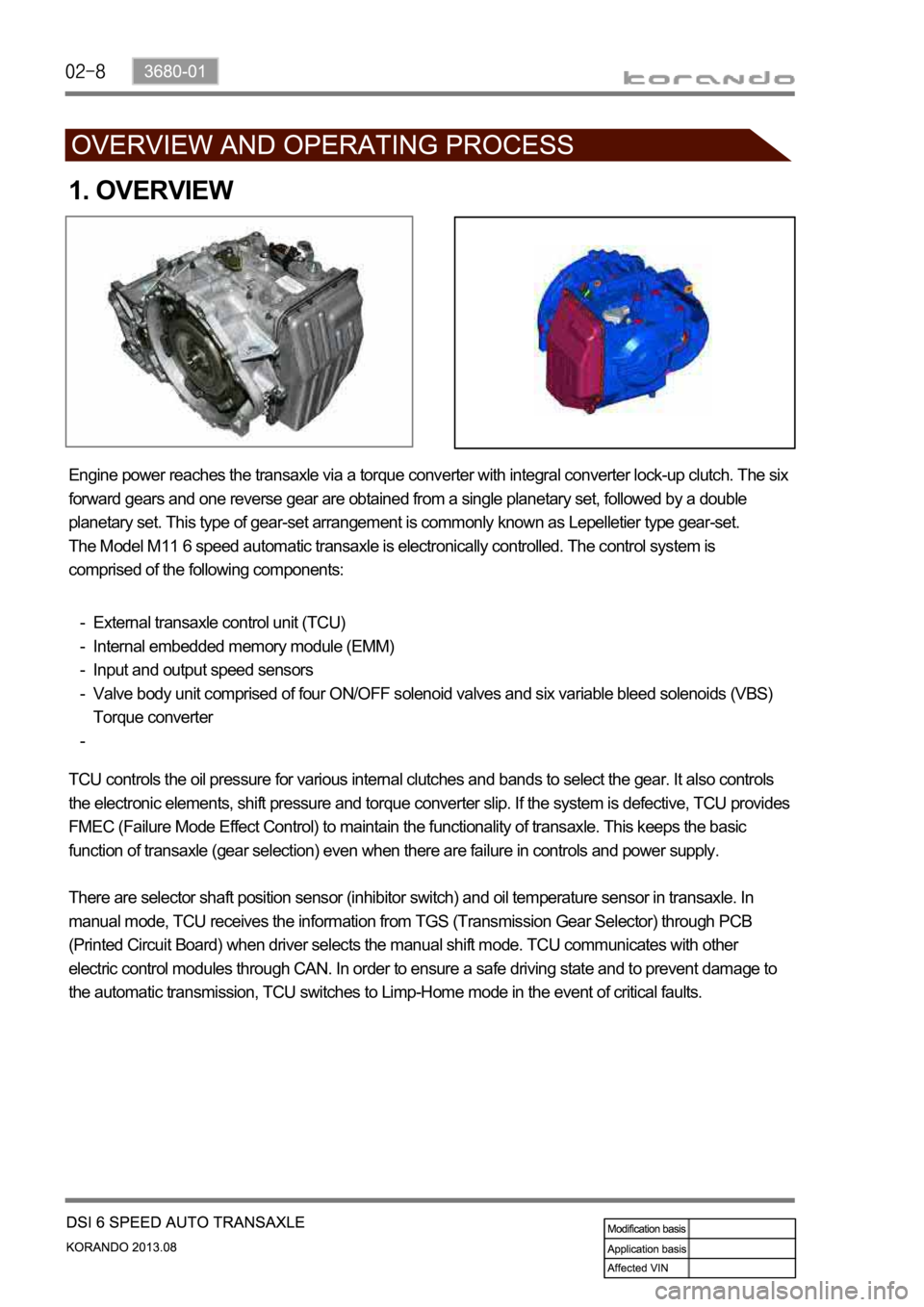
1. OVERVIEW
Engine power reaches the transaxle via a torque converter with integral converter lock-up clutch. The six
forward gears and one reverse gear are obtained from a single planetary set, followed by a double
planetary set. This type of gear-set arrangement is commonly known as Lepelletier type gear-set.
The Model M11 6 speed automatic transaxle is electronically controlled. The control system is
comprised of the following components:
External transaxle control unit (TCU)
Internal embedded memory module (EMM)
Input and output speed sensors
Valve body unit comprised of four ON/OFF solenoid valves and six variable bleed solenoids (VBS)
Torque converter -
-
-
-
-
TCU controls the oil pressure for various internal clutches and bands to select the gear. It also controls
the electronic elements, shift pressure and torque converter slip. If the system is defective, TCU provides
FMEC (Failure Mode Effect Control) to maintain the functionality of transaxle. This keeps the basic
function of transaxle (gear selection) even when there are failure in controls and power supply.
There are selector shaft position sensor (inhibitor switch) and oil temperature sensor in transaxle. In
manual mode, TCU receives the information from TGS (Transmission Gear Selector) through PCB
(Printed Circuit Board) when driver selects the manual shift mode. TCU communicates with other
electric control modules through CAN. In order to ensure a safe driving state and to prevent damage to
the automatic transmission, TCU switches to Limp-Home mode in the event of critical faults.
Page 1016 of 1336

3) Shift Map Selection
The driver can manually select between normal (S) and winter modes (W) via the mode switch.
Depending on the transaxle temperature, uphill and downhill grades and altitude, shift maps will be
selected by the TCU to suit the driving conditions. The following maps are available.
Standard (Normal) Mode
Normal Mode is selected when the lever is in the D position with the mode switch in the normal (S)
position and the transaxle is within normal temperature ranges. Shift schedule points are optimised for
fuel efficiency and general driving conditions.
Uphill and Downhill Mode
In this mode, depending on the load of the vehicle, adaptive shift maps are selected to progressively
adjust the shift points and torque converter lock points.
Altitude Mode
Shift points are automatically adjusted at higher altitudes to compensate for changes in engine torque
where the torque produced by the engine is greatly reduced by the effects of reduced barometric
pressure and temperature.
Winter (W) Mode
When winter mode is selected, starting in second gear is facilitated and the WINTER mode indicator
light is switched ON. To prevent wheel spin on slippery surfaces, the transmission will not allow first gear
unless manually overridden.
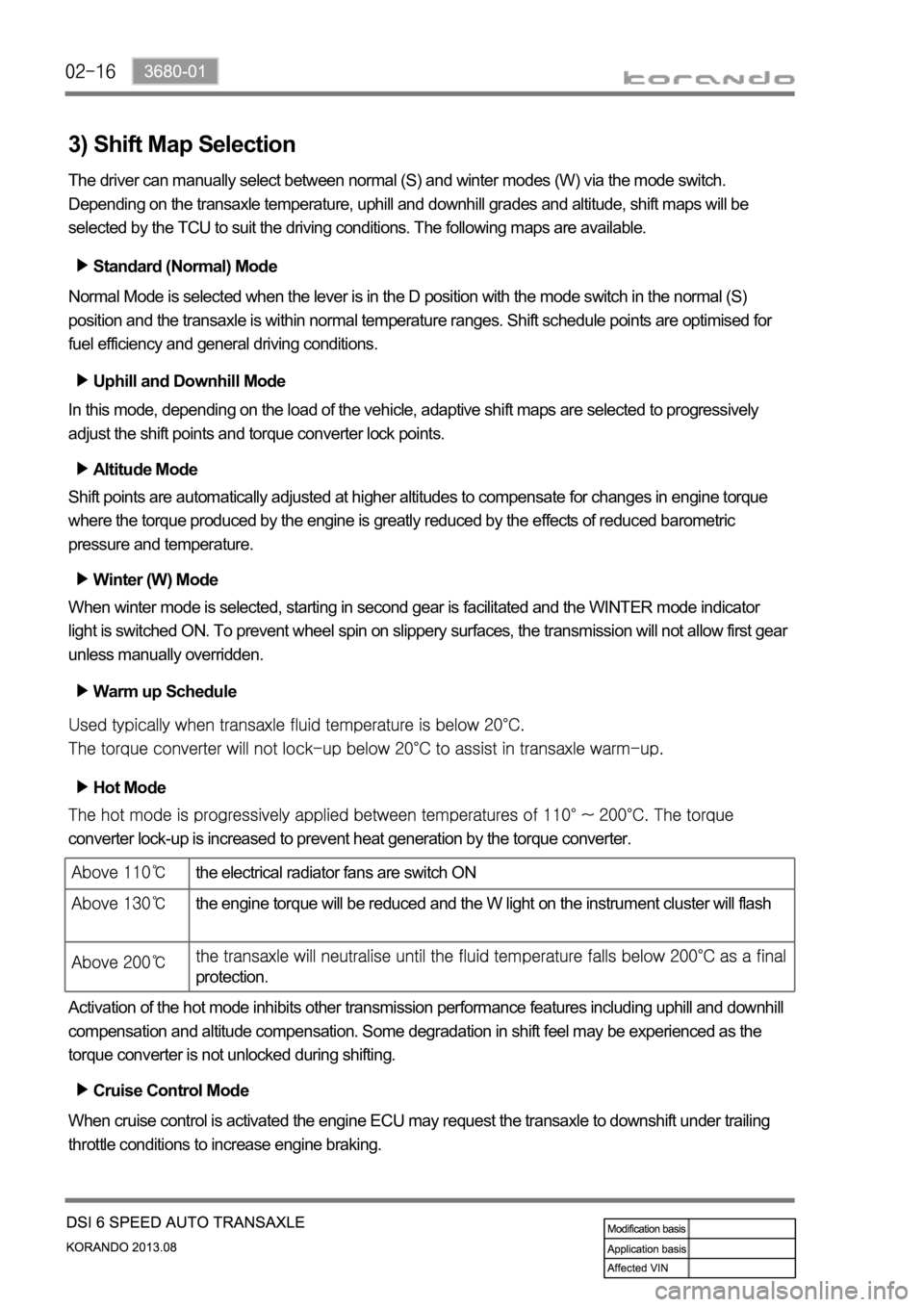
Warm up Schedule
Hot Mode
converter lock-up is increased to prevent heat generation by the torque converter.
Activation of the hot mode inhibits other transmission performance features including uphill and downhill
compensation and altitude compensation. Some degradation in shift feel may be experienced as the
torque converter is not unlocked during shifting.
Cruise Control Mode
When cruise control is activated the engine ECU may request the transaxle to downshift under trailing
throttle conditions to increase engine braking.
the electrical radiator fans are switch ON
the engine torque will be reduced and the W light on the instrument cluster will flash
protection.
Page 1029 of 1336

3660-01
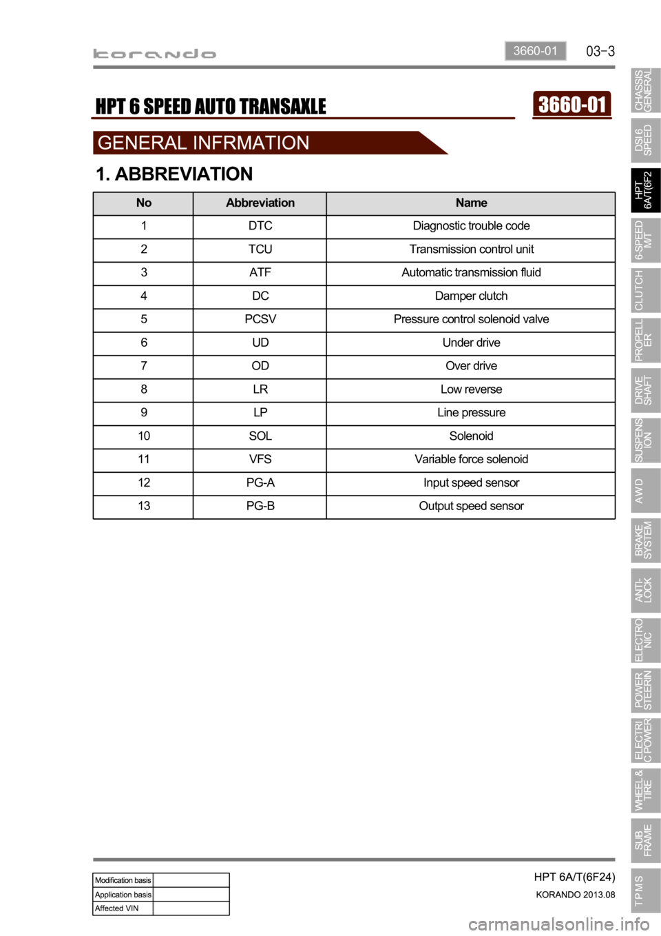
1. ABBREVIATION
No Abbreviation Name
1 DTC Diagnostic trouble code
2 TCU Transmission control unit
3 ATF Automatic transmission fluid
4 DC Damper clutch
5 PCSV Pressure control solenoid valve
6 UD Under drive
7OD Over drive
8 LR Low reverse
9 LP Line pressure
10 SOL Solenoid
11 VFS Variable force solenoid
12 PG-A Input speed sensor
13 PG-B Output speed sensor