Page 1153 of 1336

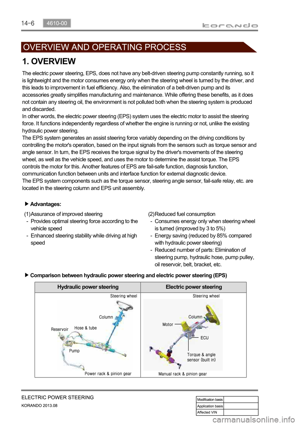
Hydraulic power steering Electric power steering
1. OVERVIEW
The electric power steering, EPS, does not have any belt-driven steering pump constantly running, so it
is lightweight and the motor consumes energy only when the steering wheel is turned by the driver, and
this leads to improvement in fuel efficiency. Also, the elimination of a belt-driven pump and its
accessories greatly simplifies manufacturing and maintenance. While offering these benefits, as it does
not contain any steering oil, the environment is not polluted both when the steering system is produced
and discarded.
In other words, the electric power steering (EPS) system uses the electric motor to assist the steering
force. It functions independently regardless of whether the engine is running or not, unlike the existing
hydraulic power steering.
The EPS system generates an assist steering force variably depending on the driving conditions by
controlling the motor's operation, based on the input signals from the sensors such as torque sensor and
angle sensor. In turn, the EPS receives the torque signal by the driver's movements of the steering
wheel, as well as the vehicle speed, and uses the motor to determine the assist torque. The EPS
controls the motor for this. Another features of EPS are fail-safe function, diagnosis function,
communication function between units and interface function for external diagnostic device.
The EPS system components such as the torque sensor, steering angle sensor, fail-safe relay, etc. are
located in the steering column and EPS unit assembly.
Advantages:
Assurance of improved steering
Provides optimal steering force according to the
vehicle speed
Enhanced steering stability while driving at high
speed (1)
-
-Reduced fuel consumption
Consumes energy only when steering wheel
is turned (improved by 3 to 5%)
Energy saving (reduced by 85% compared
with hydraulic power steering)
Reduced number of parts: Elimination of
steering pump, hydraulic hose, pump pulley,
oil reservoir, belt, bracket, etc. (2)
-
-
-
Comparison between hydraulic power steering and electric power steering (EPS)
Page 1155 of 1336
4170-00
1. SPECIFICATION
Description Specification Remark
Tire16 inch 215 / 65R 16 Standard
17 inch 225 / 60R 17 Optional
18 inch 225 / 55R 18 Optional
Tire inflation pressure32psi -
Wheel16 inch 6.5 J X 16 Standard
17 inch 6.5 J X 17 Optional
18 inch 6.5 J X 18 Optional
Balance weightInner: Clip-on type
Outer: Adhesive type-
-
Tightening torquse of wheel bolt127.4 ~ 156.8 Nm 17mm X 5
(Length:56.5 mm)
Page 1158 of 1336

1. OVERVIEW
A radial tire uses a cord angle of 90 degrees. That is, the cord material runs in a radial or direct line from
one bead to the other across the tread. In addition, a radial tire has a belt overwrap under the tread
surface to provide greater structural stability. The belt overwrap of a radial tire distortion while the radial
structure enables high speed driving.
Tire supports the weight of the vehicle, reduces the impact from the road and at the same time,
transmits the power to propel, brake and steer on the road. It also functions to maintain a
vessel of air.
There is wear limit mark on the tire, which protrudes as a strip shape located approximately 1.6 mm from
mark on the shoulder to let the driver find the wear mark easily. To measure the tire groove depth,
measure at any point other than the point which has a wear limit mark.
The tire is worn unevenly according to the driver's driving habit, improper servicing, low tire inflation
pressure, changed tire location, etc.
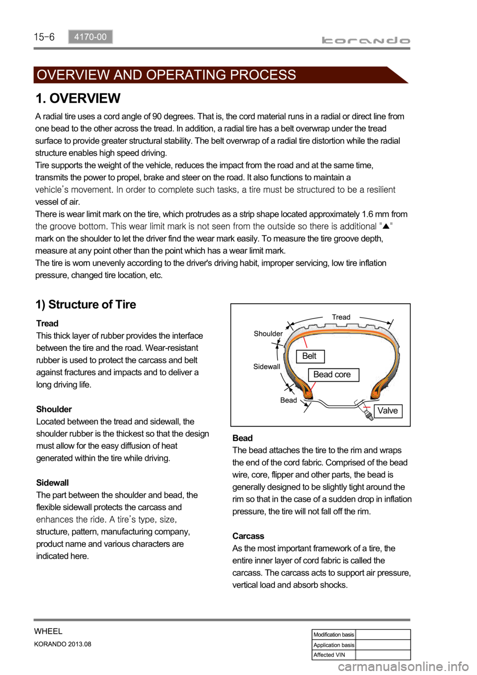
1) Structure of Tire
Tread
This thick layer of rubber provides the interface
between the tire and the road. Wear-resistant
rubber is used to protect the carcass and belt
against fractures and impacts and to deliver a
long driving life.
Shoulder
Located between the tread and sidewall, the
shoulder rubber is the thickest so that the design
must allow for the easy diffusion of heat
generated within the tire while driving.
Sidewall
The part between the shoulder and bead, the
flexible sidewall protects the carcass and
structure, pattern, manufacturing company,
product name and various characters are
indicated here. Bead
The bead attaches the tire to the rim and wraps
the end of the cord fabric. Comprised of the bead
wire, core, flipper and other parts, the bead is
generally designed to be slightly tight around the
rim so that in the case of a sudden drop in inflation
pressure, the tire will not fall off the rim.
Carcass
As the most important framework of a tire, the
entire inner layer of cord fabric is called the
carcass. The carcass acts to support air pressure,
vertical load and absorb shocks.
Valve
Belt
Bead core
Page 1162 of 1336

If weight is not equally distributed around the wheel, unbalance centrifugal force by the wheel rotation
produces vibration. As the centrifugal force is produced proportional to the square of the rotating speed,
the wheel weight should be balanced even at high speed. There are two types of the tire and wheel
balancing: static and dynamic. Abnormal vibration may also occur due to unbalanced rigidity or size of
tires.
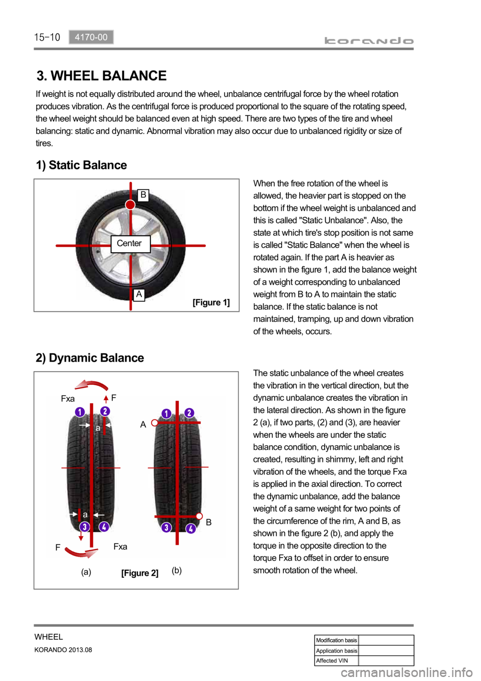
1) Static Balance
When the free rotation of the wheel is
allowed, the heavier part is stopped on the
bottom if the wheel weight is unbalanced and
this is called "Static Unbalance". Also, the
state at which tire's stop position is not same
is called "Static Balance" when the wheel is
rotated again. If the part A is heavier as
shown in the figure 1, add the balance weight
of a weight corresponding to unbalanced
weight from B to A to maintain the static
balance. If the static balance is not
maintained, tramping, up and down vibration
of the wheels, occurs.
2) Dynamic Balance
The static unbalance of the wheel creates
the vibration in the vertical direction, but the
dynamic unbalance creates the vibration in
the lateral direction. As shown in the figure
2 (a), if two parts, (2) and (3), are heavier
when the wheels are under the static
balance condition, dynamic unbalance is
created, resulting in shimmy, left and right
vibration of the wheels, and the torque Fxa
is applied in the axial direction. To correct
the dynamic unbalance, add the balance
weight of a same weight for two points of
the circumference of the rim, A and B, as
shown in the figure 2 (b), and apply the
torque in the opposite direction to the
torque Fxa to offset in order to ensure
smooth rotation of the wheel.
Center
A
B
a
a
Fxa
Fxa F
F
A
B
(a)(b)
[Figure 1]
[Figure 2]
3. WHEEL BALANCE
Page 1163 of 1336
4012-00
Unit Construction
Front sub
frame
Rear sub
frame
(4WD)
Rear sub
frame
(2WD)
1. SPECIFICATION
Body mounting:
4-points bush
Transaxle mounting:
2-points bush
Weight: 22.37 kg 1.
2.
3.
Body mounting:
4-points bush
Axle mounting:
4-points bush
Weight: 16.61 kg 1.
2.
3.
Body mounting:
40 points direct
mounting
Spring link:
Direct mounting
without bracket on
rear cross member
Weight: 12.74 kg 1.
2.
3.
BRKT-ENG MTG RRBRKT-ENG MTG FRT
Page 1281 of 1336
1) Child Restraint System Type
There are 2 types in the child restraint system.
- Fixing using seat belt
- Fixing using ISOFIX (for the vehicle with ISOFIX system)
2) Child Restraint System Fixing Type
4. CHILD RESTRAINT SYSTEM (ISO FIX)
Item Weight AgeFixing
methodRear
LH/RH
seat Passenger seat/
Rear center seat
Reversed seat< 10kg 6 to 9 months Seat belt U/SU X
< 13kg 12 to 15 months Seat belt U/SU X
Front face seat 9~18kg 9 to 48 monthsSeat belt /
ISOFIX seatU/UF/SU X
Booster seat 15~25kg 4 to 6 years Seat belt U X
Booster cushion 22~36kg 6 to 11 years Seat belt U X
U: General child restraint system which should be fixed with the seat belt approved by official institute.
UF/SU: General child restraint system which should be fixed with the ISOFIX system approved by
official/semiofficial institute.
X: Seat which is not allowed to use child restraint system. -
-
-