Page 1200 of 1336

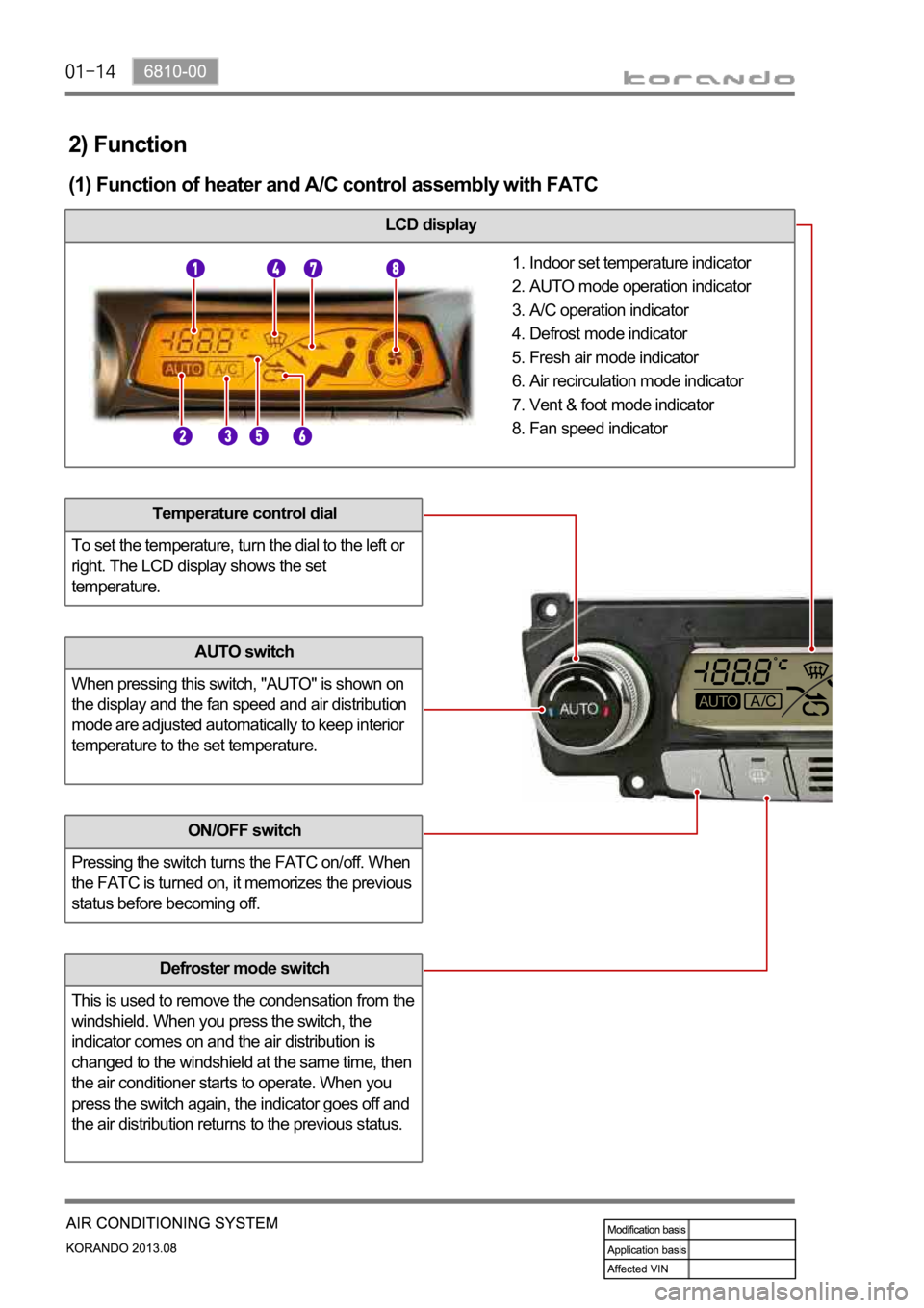
2) Function
(1) Function of heater and A/C control assembly with FATC
LCD display
Indoor set temperature indicator
AUTO mode operation indicator
A/C operation indicator
Defrost mode indicator
Fresh air mode indicator
Air recirculation mode indicator
Vent & foot mode indicator
Fan speed indicator 1.
2.
3.
4.
5.
6.
7.
8.
Temperature control dial
To set the temperature, turn the dial to the left or
right. The LCD display shows the set
temperature.
AUTO switch
When pressing this switch, "AUTO" is shown on
the display and the fan speed and air distribution
mode are adjusted automatically to keep interior
temperature to the set temperature.
ON/OFF switch
Pressing the switch turns the FATC on/off. When
the FATC is turned on, it memorizes the previous
status before becoming off.
Defroster mode switch
This is used to remove the condensation from the
windshield. When you press the switch, the
indicator comes on and the air distribution is
changed to the windshield at the same time, then
the air conditioner starts to operate. When you
press the switch again, the indicator goes off and
the air distribution returns to the previous status.
Page 1209 of 1336
6810-00
(6) A/C control
The air conditioner is controlled by the A/C compressor of the engine ECU according to the signal from
the heater and A/C control assembly. The driver can see the air conditioner operation through the LCD
display and the indicator of the A/C switch.
Manual control
Pressing the A/C switch or selecting defrost mode turns on the A/C.
Auto control
The A/C is controlled in accordance with the indoor temperature and ambient temperature.
or below) in winter, the compressor is turned off to protect the A/C compressor.
A/C switch
LCD display (A/C operation view)
Page 1214 of 1336
4. MTC SYSTEM OPERATION PROCESS
1) Input/Output Factors
The MTC (Manual Temperature Control) system controls all the actuator and blower motor by the driver.
The heater and A/C control assembly with MTC has the dials and switches with the indicators so that the
driver can know the air conditioning system's operation.
Page 1215 of 1336

6810-00
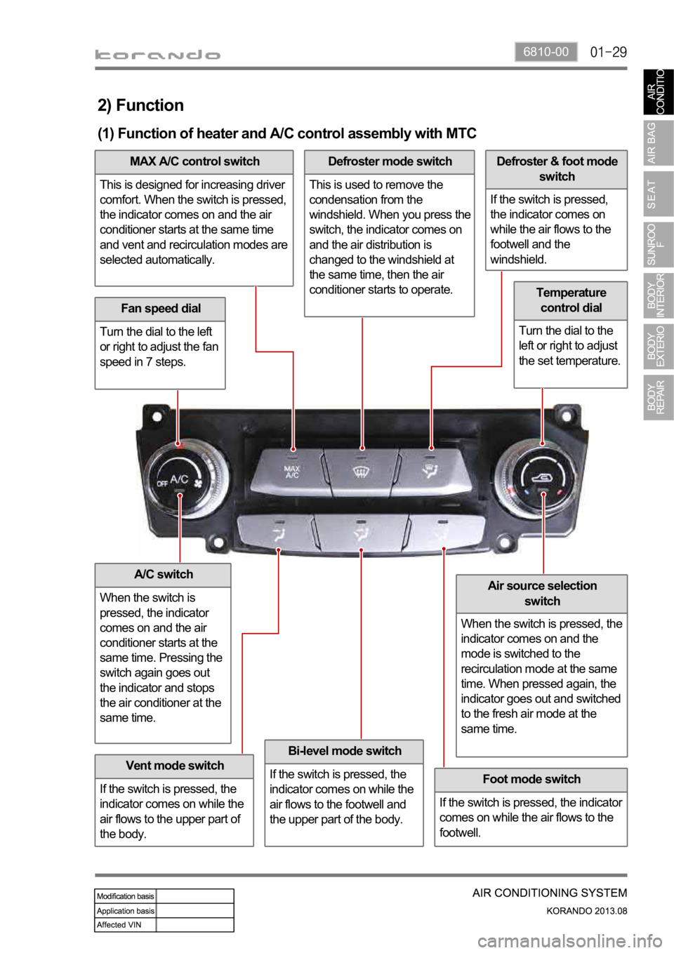
2) Function
(1) Function of heater and A/C control assembly with MTC
Fan speed dial
Turn the dial to the left
or right to adjust the fan
speed in 7 steps.
A/C switch
When the switch is
pressed, the indicator
comes on and the air
conditioner starts at the
same time. Pressing the
switch again goes out
the indicator and stops
the air conditioner at the
same time.
Vent mode switch
If the switch is pressed, the
indicator comes on while the
air flows to the upper part of
the body.
Bi-level mode switch
If the switch is pressed, the
indicator comes on while the
air flows to the footwell and
the upper part of the body.
MAX A/C control switch
This is designed for increasing driver
comfort. When the switch is pressed,
the indicator comes on and the air
conditioner starts at the same time
and vent and recirculation modes are
selected automatically.Defroster mode switch
This is used to remove the
condensation from the
windshield. When you press the
switch, the indicator comes on
and the air distribution is
changed to the windshield at
the same time, then the air
conditioner starts to operate.Defroster & foot mode
switch
If the switch is pressed,
the indicator comes on
while the air flows to the
footwell and the
windshield.
Foot mode switch
If the switch is pressed, the indicator
comes on while the air flows to the
footwell.
Temperature
control dial
Turn the dial to the
left or right to adjust
the set temperature.
Air source selection
switch
When the switch is pressed, the
indicator comes on and the
mode is switched to the
recirculation mode at the same
time. When pressed again, the
indicator goes out and switched
to the fresh air mode at the
same time.
Page 1217 of 1336
6810-00
(4) Air source control
When pressing the air source selection switch, the air source mode is changed via the intake actuator's
operation. The air source mode is switched between the fresh air and recirculation alternatively each
time the switch is pressed. You can see the air source mode through the switch's indicator. (the indicator
comes on at recirculation mode)
Control by vehicle speed
The air source selection is controlled in accordance with the vehicle speed while driving. Operating
conditions and control process are as follows:
When the PTC heater operates at fresh air mode in winter
When the vehicle speed is 45 km/h or lower in fresh air mode, the air source door is open 30% of its
maximum opening. If the vehicle speed is 65 km/h or more, then the air source door is completely
open. -
-
However, the electronic fan should be more than 7.5 V.
Air source selection switch
Page 1220 of 1336
(6) A/C control
The air conditioner is operated at the defroster mode and MAX air conditioner mode and when the A/C
switch is turned to "ON" position. It is controlled by the A/C compressor of the engine ECU according to
the signal from the heater and A/C control assembly. The driver can see that the A/C has been activated
when an indicator lamps at the A/C switch and MAX A/C switch comes on. If the intake sensor detects
the freezing of the evaporator core, it stops the air conditioner by turning off the compressor.
MAX A/C control
This is designed for increasing driver comfort. When the switch is pressed, the air conditioner is
operated and vent and recirculation modes are selected automatically. The discharge temperature and
fan speed are regulated depending on the driver's choice.
A/C switch
MAX A/C control switch
Page 1221 of 1336

6810-00
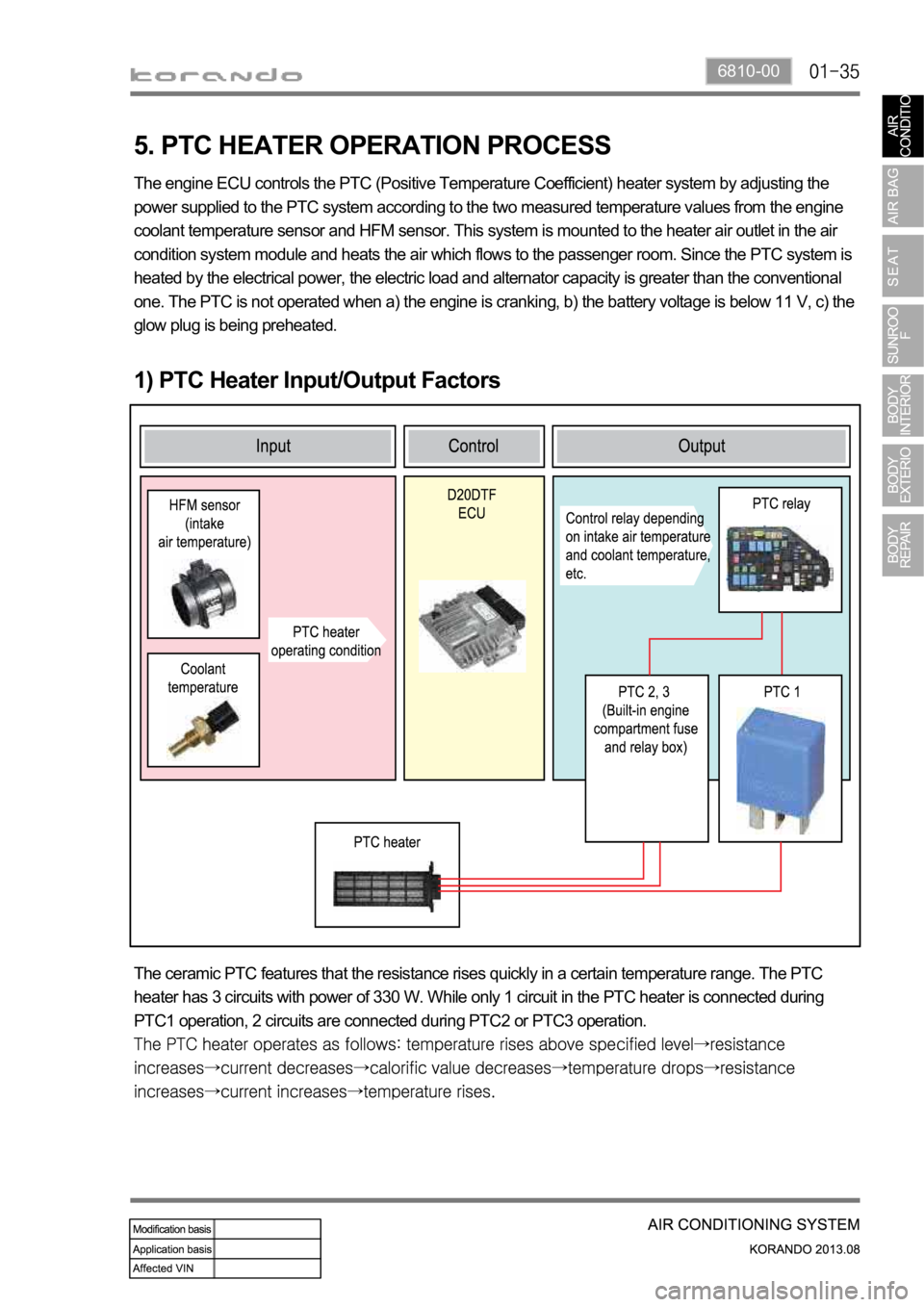
5. PTC HEATER OPERATION PROCESS
1) PTC Heater Input/Output Factors
The engine ECU controls the PTC (Positive Temperature Coefficient) heater system by adjusting the
power supplied to the PTC system according to the two measured temperature values from the engine
coolant temperature sensor and HFM sensor. This system is mounted to the heater air outlet in the air
condition system module and heats the air which flows to the passenger room. Since the PTC system is
heated by the electrical power, the electric load and alternator capacity is greater than the conventional
one. The PTC is not operated when a) the engine is cranking, b) the battery voltage is below 11 V, c) the
glow plug is being preheated.
The ceramic PTC features that the resistance rises quickly in a certain temperature range. The PTC
heater has 3 circuits with power of 330 W. While only 1 circuit in the PTC heater is connected during
PTC1 operation, 2 circuits are connected during PTC2 or PTC3 operation.
Page 1222 of 1336
2) Control Condition For PTC Heater
Operation Operating condition PTC heater status
HI mode operation
(PTC2, 3)PTC heater operates in
"HIGH" mode if operating
conditions are met
LO mode operation
(PTC1)PTC heater operates in
"LOW" mode if operating
conditions are met
Conditions for
deactivating
Air conditioner blower switch OFF
When the ambient temperature sensor is
faulty (short or open circuit in the wiring)
Engine is cranking
Battery voltage is 11 V or less
Glow plug is being preheated (Glow indicator
comes on) -
-
-
-
-
-
-
-
-
Conditions for PTC heater "LOW" operation mode (2nd step)