2013 SKODA ROOMSTER heating
[x] Cancel search: heatingPage 61 of 219
WARNING (Continued)■Please note that transporting heavy objects alters the handling properties
of the vehicle due to the displacement of the centre of gravity – risk of acci-
dent! The speed and style of driving must be adjusted accordingly.■
If the items of luggage or objects are attached to the lashing eyes with un-
suitable or damaged lashing straps, injuries can occur in the event of braking
manoeuvres or accidents. To prevent items of luggage from being thrown for-
ward, always use suitable lashing straps which must be firmly attached to the lashing eyes.
■
The transported items must be stowed in such a way that no objects are
able to slip forward on sudden driving or braking manoeuvres – risk of injury!
■
When transporting fastened objects which are sharp and dangerous in the
boot that has been enlarged by folding the rear seats forward, ensure the safety of the passengers transported on the other rear seats » page 125, Cor-
rect seated position for the passengers in the rear seats .
■
If the rear seat next to the folded forward seat is occupied, ensure maxi-
mum safety, e.g. by placing the goods to be transported in such a way that the
seat is prevented from folding back in case of a rear collision.
■
Never drive with the luggage compartment lid open or ajar, as otherwise ex-
haust gases may get into the interior of the vehicle – risk of poisoning!
■
Under no circumstances should the permissible axle loads and the permissi-
ble total vehicle weight be exceeded – risk of accident!
■
Never transport people in the boot!
CAUTION
Please ensure that the heating elements for the rear window heater are not dam-
aged as a result of abrasive objects.
Note
Tyre pressure must be adjusted to the load » page 173, Service life of tyres .
Class N1 vehicles
First read and observe the introductory information and safety warn-
ings
on page 57.
On class N1 vehicles, which are not fitted with a protective grille, a lashing set which complies with the standard EN 12195 (1 - 4) must be used for fastening the
load.
The proper functioning of the electrical system is essential for the safe operation
of the vehicle. It is important to ensure that it is not damaged during modifica-
tions or when loading or unloading the luggage compartment.
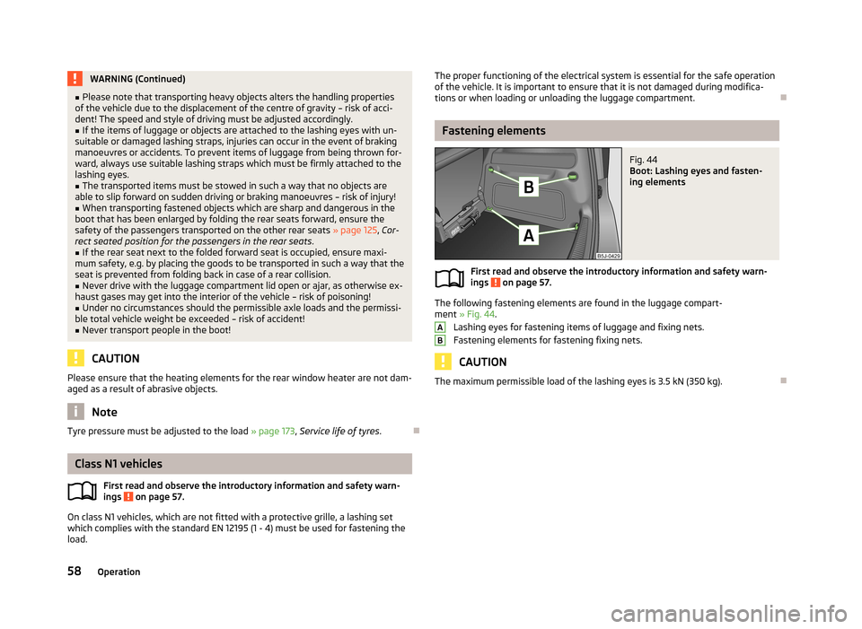
Fastening elements
Fig. 44
Boot: Lashing eyes and fasten-
ing elements
First read and observe the introductory information and safety warn-
ings on page 57.
The following fastening elements are found in the luggage compart-
ment » Fig. 44 .
Lashing eyes for fastening items of luggage and fixing nets.
Fastening elements for fastening fixing nets.
CAUTION
The maximum permissible load of the lashing eyes is 3.5 kN (350 kg).
AB58Operation
Page 63 of 219
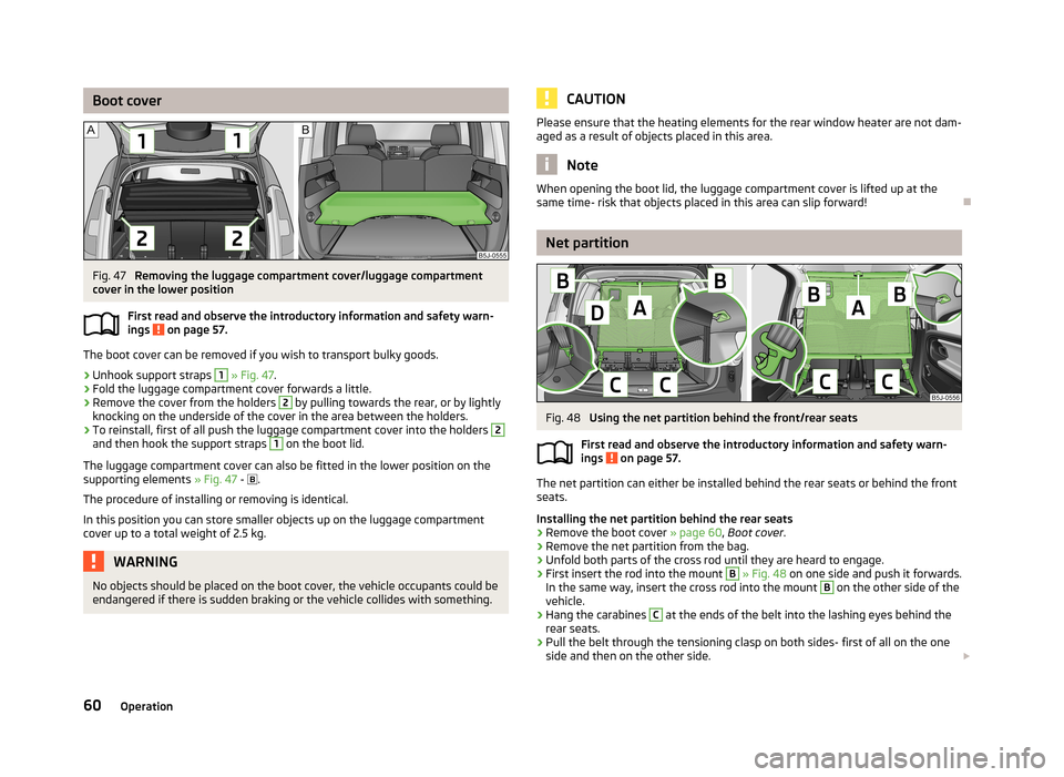
Boot coverFig. 47
Removing the luggage compartment cover/luggage compartment
cover in the lower position
First read and observe the introductory information and safety warn-
ings
on page 57.
The boot cover can be removed if you wish to transport bulky goods.
›
Unhook support straps
1
» Fig. 47 .
›
Fold the luggage compartment cover forwards a little.
›
Remove the cover from the holders
2
by pulling towards the rear, or by lightly
knocking on the underside of the cover in the area between the holders.
›
To reinstall, first of all push the luggage compartment cover into the holders
2
and then hook the support straps
1
on the boot lid.
The luggage compartment cover can also be fitted in the lower position on the
supporting elements » Fig. 47 -
.
The procedure of installing or removing is identical. In this position you can store smaller objects up on the luggage compartment cover up to a total weight of 2.5 kg.
WARNINGNo objects should be placed on the boot cover, the vehicle occupants could be
endangered if there is sudden braking or the vehicle collides with something.CAUTIONPlease ensure that the heating elements for the rear window heater are not dam-
aged as a result of objects placed in this area.
Note
When opening the boot lid, the luggage compartment cover is lifted up at the
same time- risk that objects placed in this area can slip forward!
Net partition
Fig. 48
Using the net partition behind the front/rear seats
First read and observe the introductory information and safety warn-
ings
on page 57.
The net partition can either be installed behind the rear seats or behind the front
seats.
Installing the net partition behind the rear seats
›
Remove the boot cover » page 60, Boot cover .
›
Remove the net partition from the bag.
›
Unfold both parts of the cross rod until they are heard to engage.
›
First insert the rod into the mount
B
» Fig. 48 on one side and push it forwards.
In the same way, insert the cross rod into the mount
B
on the other side of the
vehicle.
›
Hang the carabines
C
at the ends of the belt into the lashing eyes behind the
rear seats.
›
Pull the belt through the tensioning clasp on both sides- first of all on the one side and then on the other side.
60Operation
Page 72 of 219
stowage compartments in the luggage73Flexible storage compartment73WARNING■Do not place anything on the dash panel. These objects might slide or fall
down while you are driving (under acceleration or when cornering) and could
distract you from the traffic - there is a risk of an accident.■
Make sure that no objects from the centre console or from other storage
compartments can get into the driver's footwell while you are driving. You
would then no longer be able to apply the brakes or operate the clutch or ac-
celerator pedal – there is a risk of an accident.
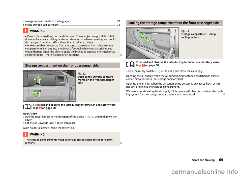
Storage compartment on the front passenger side
Fig. 62
Dash panel: Storage compart-
ments on the front passenger
side
First read and observe the introductory information and safety warn- ings on page 68.
Open/close
›
Pull the cover handle in the direction of the arrow » Fig. 62
and fold down the
cover.
›
Lift the lid upwards until it clicks into place.
A pin holder is located inside the lower flap.
WARNINGThe storage compartments must always be closed when driving for safety
reasons.
Cooling the storage compartment on the front passenger sideFig. 63
Storage compartment: Using
cooling system
First read and observe the introductory information and safety warn-
ings on page 68.
›
Use the rotary switch » Fig. 63 to open and close the air supply.
Opening the air supply when the air conditioning system is switched on allows
cooled air to flow into the storage compartment.
Opening the air inlet when the air conditioning system is on causes fresh or inte-rior air to flow into the storage compartment.
We recommend closing the air supply if it is operated in heating mode or the cool-ing system for the storage compartment is not being used.
69Seats and stowing
Page 80 of 219

Heating and air-conditioning
Heating, ventilation, cooling
Introduction
This chapter contains information on the following subjects:
Air outlets
77
Using the air conditioning system economically
78
Operational problems
78
The heating effect is dependent upon the coolant temperature, thus full heat
output only occurs when the engine has reached its operating temperature.
If the cooling system is switched on, the temperature and air humidity drops in
the vehicle. The cooling system prevents the windows from misting up when out- side temperatures are particularly low.
It is possible to briefly activate recirculated air mode to enhance the cooling ef- fect.
Please refer to the information regarding recirculated air mode for the air-condi- tioning system » page 82 or for Climatronic » page 84.
WARNINGFor your own safety and that of other road users, ensure that all the windows
are free of ice, snow and misting. Please familiarize yourself about how to cor- rectly operate the heating and ventilation systems, how to demist and defrost
the windows, as well as with the cooling mode.
CAUTION
■ The air inlet in front of the windscreen must be free (e.g. of ice, snow or leaves)
to ensure that the heating and cooling system operates properly.■
After switching on the cooling Condensation from the evaporator of the air con-
ditioning may drip down and form a puddle below the vehicle. This is not a leak.
Note■ The exhaust air streams out through vents at the rear of the luggage compart-
ment.■
We recommend that you do not smoke in the vehicle when the recirculating air
mode is operating since the smoke which is drawn at the evaporator from the in- terior of the vehicle forms deposits in the evaporator of the air conditioning sys-tem. This produces a permanent odour when the air conditioning system is oper-ating which can only be eliminated through considerable effort and expense (re-
placement of compressor).
Air outlets
Fig. 80
Air outlet vents
First read and observe the introductory information and safety warn-
ings
on page 77.
Warmed, not warmed fresh or cooled air will flow out of the opened air outlet
vents according to the setting of the control and the outside atmospheric condi-
tions.
The direction of airflow can be adjusted using the air outlet vents 3 and
4 » Fig. 80 and the outlets can also be opened and closed individually.
Open the air outlet vents 3 and 4
›
Turn the vertical wheel (air vents 3) » Fig. 80 or the horizontal wheel (air outlet
nozzles 4) to the
position.
77Heating and air-conditioning
Page 81 of 219

Close air outlet vents 3 and 4›Turn the vertical wheel (air vents 3) » Fig. 80 or the horizontal wheel (air outlet
nozzles 4) to the 0 position.
Change air flow of air outlet vents 3 and 4›
In order to change the strength of the air flow, swivel the horizontal lamellas with the aid of the moveable adjuster » Fig. 80.
›
In order to change the lateral direction of the air flow, swivel the vertical lamel-
las with the aid of the moveable adjuster.
Set the air supply to the individual vents with the air distribution control
C
» Fig. 81 on page 79.
Note
Do not cover the air outlet vents with objects of any kind.
Using the air conditioning system economically
First read and observe the introductory information and safety warn-ings
on page 77.
The air conditioning system compressor uses power from the engine when in
cooling mode, which will affect the fuel consumption.
It recommended to open the windows or the doors of a vehicle for which the inte-rior has been strongly heated through the effect of direct sunlight in order to al-
low the heated air to escape.
The cooling system should not be switched on if the windows are open.
For the sake of the environment
Pollutant emissions are also lower when fuel is being saved » page 104.
Operational problems
First read and observe the introductory information and safety warn-
ings
on page 77.
If the cooling system does not operate at outside temperatures higher than +5 °C,
there is a problem in the system. The reasons for this may be.
› One of the fuses has blown. Check the fuse and replace if necessa-
ry » page 191 .
› The cooling system has switched off automatically for a short time because the
coolant temperature of the engine is too hot » page 11.
If you are not able to resolve the operational problem yourself, or if the cooler
output has reduced, switch off the cooling system and seek assistance from a
specialist garage.
Heating
Introduction
This chapter contains information on the following subjects:
Operation
79
Setting
79
Recirculated air mode
80
78Operation
Page 82 of 219
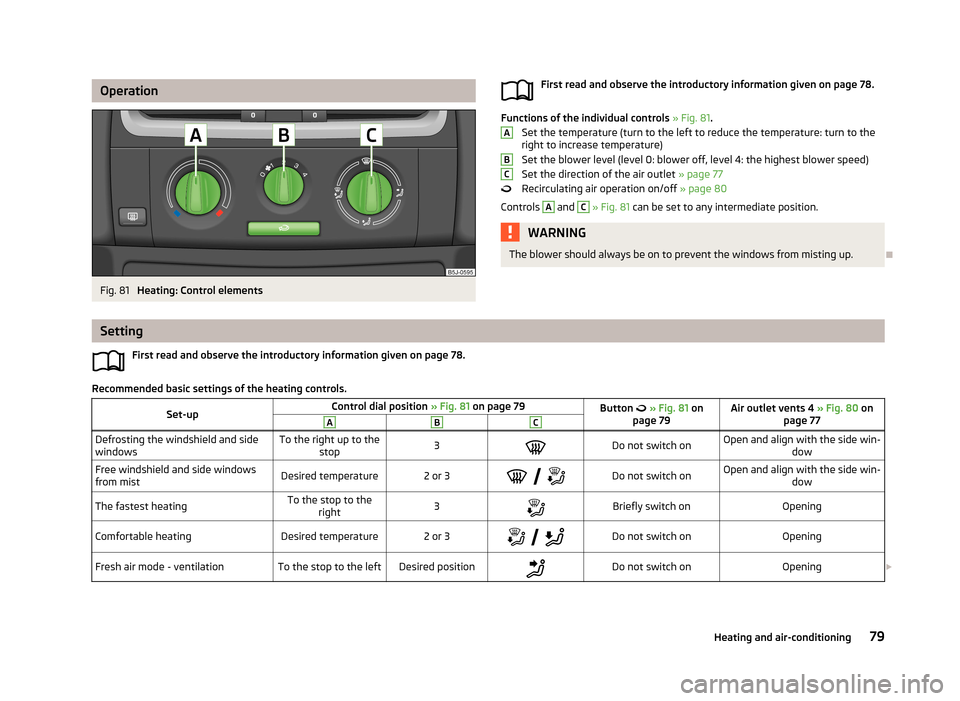
OperationFig. 81
Heating: Control elements
First read and observe the introductory information given on page 78.
Functions of the individual controls » Fig. 81 .
Set the temperature (turn to the left to reduce the temperature: turn to the right to increase temperature)
Set the blower level (level 0: blower off, level 4: the highest blower speed) Set the direction of the air outlet » page 77
Recirculating air operation on/off » page 80
Controls
A
and
C
» Fig. 81 can be set to any intermediate position.
WARNINGThe blower should always be on to prevent the windows from misting up.
ABC
Setting
First read and observe the introductory information given on page 78.
Recommended basic settings of the heating controls.
Set-upControl dial position » Fig. 81 on page 79Button » Fig. 81 on
page 79Air outlet vents 4 » Fig. 80 on
page 77ABCDefrosting the windshield and side
windowsTo the right up to the stop3Do not switch onOpen and align with the side win- dowFree windshield and side windows
from mistDesired temperature2 or 3
Do not switch onOpen and align with the side win-
dowThe fastest heatingTo the stop to theright3Briefly switch onOpeningComfortable heatingDesired temperature2 or 3
Do not switch onOpeningFresh air mode - ventilationTo the stop to the leftDesired positionDo not switch onOpening 79Heating and air-conditioning
Page 83 of 219

We recommend that you leave the air outlet vents 3 » Fig. 80 on page 77 in the
open position in all operating modes.
Note
If the air distribution is set only to the windows, the entire volume of air is used
to defrost the windows and thus no air will be fed to the footwell. This can limit
the heating comfort.
Recirculated air mode
First read and observe the introductory information given on page 78.
Recirculated air mode prevents polluted air from outside the vehicle getting into
the vehicle, for example when driving through a tunnel or when standing in a
traffic jam.
Switching on/off
›
Press the
button.
The indicator light in the button lights up.
›
Press the
button again.
The indicator light in the button goes out.
Recirculated air mode is switched off automatically if the air distribution control
C
» Fig. 81 on page 79 is turned to the
position. Recirculated air mode can be
switched on again from this setting by pressing the
button again.
WARNINGNever leave recirculated air mode on over a longer period of time, as “stale air”
can cause fatigue of the driver and the passengers, reduce attention levels
and also cause the windows to mist up. The risk of having an accident increa-
ses. Switch off recirculated air mode as soon as the windows start to mist up.
Air conditioning system (manual air conditioning
system)
Introduction
This chapter contains information on the following subjects: Operation
81
Setting the air conditioning system
82
Recirculated air mode
82
The cooling system operates only if the following conditions are met. The cooling system is switched on » page 81.
The engine is running.
The outside temperature is above approximately +2 °C.
The blower switch is switched on (positions 1-4).
If the desired interior temperature can also be achieved without activating the cooling system, fresh air mode should be selected.
If the coolant temperature is too high, the cooling system is switched off to en-
sure that the engine cools down.
CAUTION
■ Under certain circumstances, air at a temperature of about 5 °C can flow out of
the vents when the cooling system is switched on.■
Lengthy and uneven distribution of the air flow out of the vents (especially
around the feet) and large differences in temperature, for example, when getting
out of the vehicle, can cause susceptible individuals to catch a cold.
Note
We recommend that you have the air conditioning system cleaned by a specialist
garage once every year.80Operation
Page 84 of 219
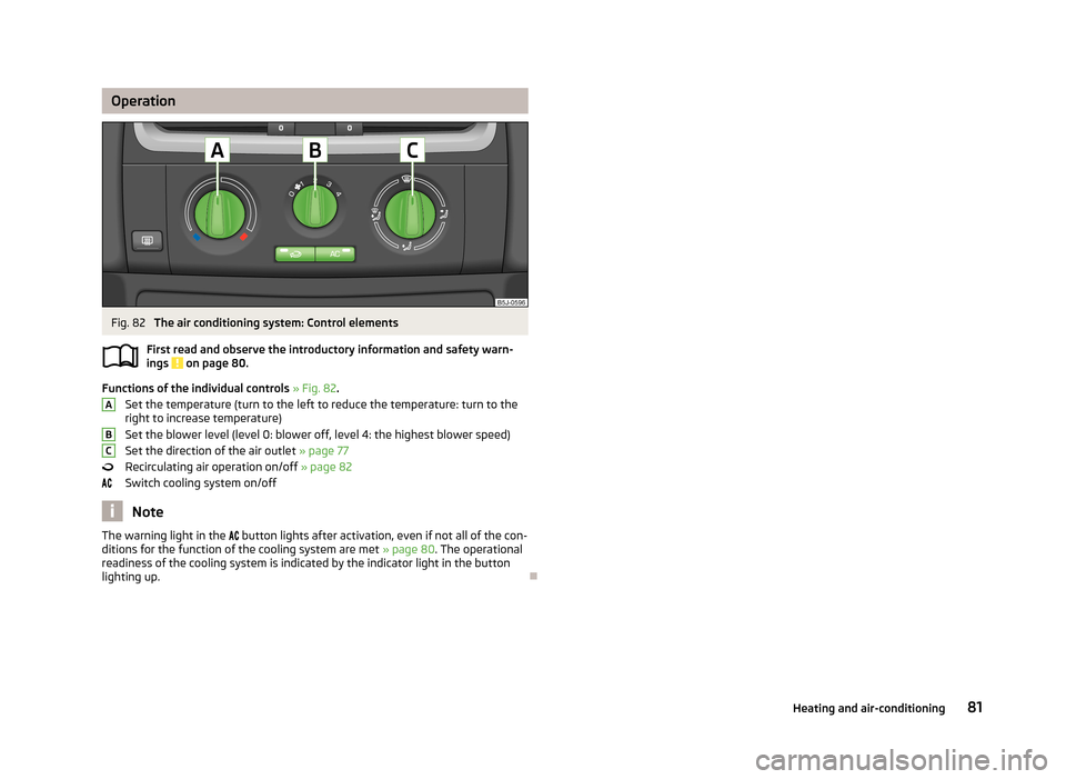
OperationFig. 82
The air conditioning system: Control elements
First read and observe the introductory information and safety warn- ings
on page 80.
Functions of the individual controls » Fig. 82 .
Set the temperature (turn to the left to reduce the temperature: turn to the right to increase temperature)
Set the blower level (level 0: blower off, level 4: the highest blower speed)
Set the direction of the air outlet » page 77
Recirculating air operation on/off » page 82
Switch cooling system on/off
Note
The warning light in the button lights after activation, even if not all of the con-
ditions for the function of the cooling system are met » page 80. The operational
readiness of the cooling system is indicated by the indicator light in the button
lighting up.
ABC81Heating and air-conditioning