Page 124 of 279

17B-124
AFTER REPAIRDeal with any faults displayed by the diagnostic tool.
Clear the computer fault memory.
Carry out a road test followed by another check with the diagnostic tool.
V2 MR-376-X76-17B050$083.mif
PETROL INJECTION
Fault finding – Interpretation of faults17B
V42 Injection
Program No.: 2A
Vdiag No.: 04, 05, 06,
14, 16, 18
DF887
PRESENT OR
STOREDBRAKE - ACCELERATOR PEDAL POSITION1.DEF: Jammed accelerator pedal detected.
2.DEF: Jammed accelerator pedal detected.
3.DEF: Inconsistency between pedal gang 1 and gang 2.
4. DEF: Fault on pedal potentiometer gangs 1 and 2.
NOTESConditions for application to a stored fault:
The fault is declared present after the ignition is switched on or with the engine running.
Deal with the stored faults (1.DEF, 2.DEF only).
Special notes:
After this fault appears:
For 3.DEF, the OBD and level 1 warning lights are illuminated.
For 2.DEF and 4.DEF, the OBD and level 2 warning lights are illuminated.
1.DEF
2.DEF
NOTESNone.
Check that the accelerator pedal is not jammed and that there is nothing impeding its operation (floor carpet, etc.).
Run TEST 9 Brake pedal switch check.
Run TEST 8 Accelerator pedal potentiometer check.
If the fault is still present, contact the Techline.
V42_V04_DF887/V42_V05_DF887/V42_V06_DF887/V42_V14_DF887/V42_V16_DF887/V42_V18_DF887
Page 134 of 279

17B-134
AFTER REPAIRDeal with any faults displayed by the diagnostic tool.
Clear the computer fault memory.
Carry out a road test followed by another check with the diagnostic tool.
V2 MR-376-X76-17B050$084.mif
PETROL INJECTION
Fault finding – Interpretation of faults17B
V42 Injection
Program No.: 2A
Vdiag No.: 04, 05, 06,
14, 16, 18
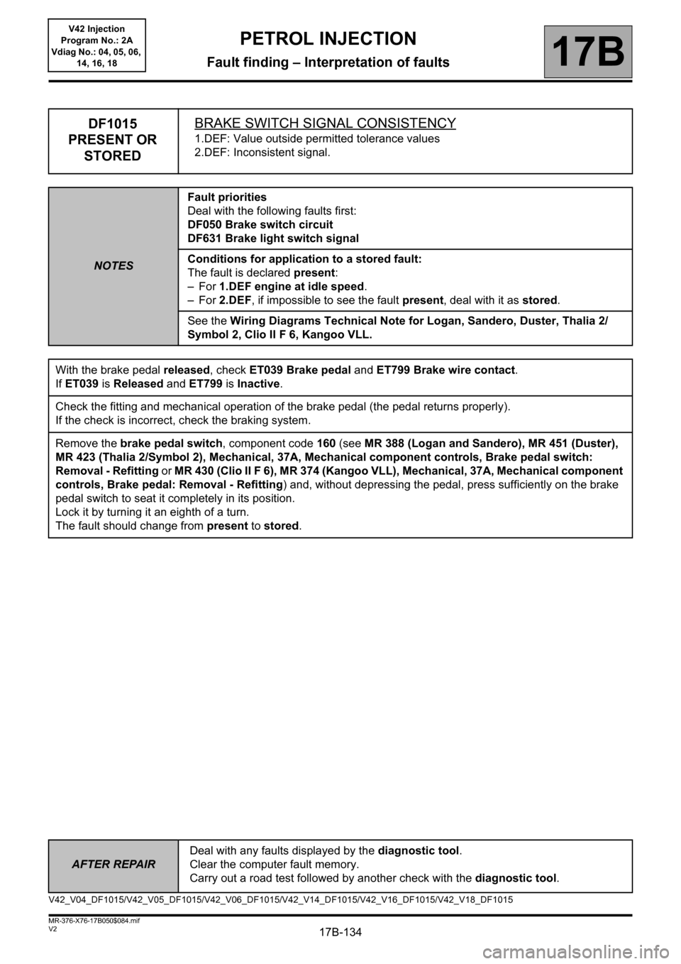
DF1015
PRESENT OR
STOREDBRAKE SWITCH SIGNAL CONSISTENCY
1.DEF: Value outside permitted tolerance values
2.DEF: Inconsistent signal.
NOTESFault priorities
Deal with the following faults first:
DF050 Brake switch circuit
DF631 Brake light switch signal
Conditions for application to a stored fault:
The fault is declared present:
–For 1.DEF engine at idle speed.
–For 2.DEF, if impossible to see the fault present, deal with it as stored.
See the Wiring Diagrams Technical Note for Logan, Sandero, Duster, Thalia 2/
Symbol 2, Clio II F 6, Kangoo VLL.
With the brake pedal released, check ET039 Brake pedal and ET799 Brake wire contact.
If ET039 is Released and ET799 is Inactive.
Check the fitting and mechanical operation of the brake pedal (the pedal returns properly).
If the check is incorrect, check the braking system.
Remove the brake pedal switch, component code 160 (see MR 388 (Logan and Sandero), MR 451 (Duster),
MR 423 (Thalia 2/Symbol 2), Mechanical, 37A, Mechanical component controls, Brake pedal switch:
Removal - Refitting or MR 430 (Clio II F 6), MR 374 (Kangoo VLL), Mechanical, 37A, Mechanical component
controls, Brake pedal: Removal - Refitting) and, without depressing the pedal, press sufficiently on the brake
pedal switch to seat it completely in its position.
Lock it by turning it an eighth of a turn.
The fault should change from present to stored.
V42_V04_DF1015/V42_V05_DF1015/V42_V06_DF1015/V42_V14_DF1015/V42_V16_DF1015/V42_V18_DF1015
Page 161 of 279
17B-161V2 MR-376-X76-17B050$100.mif
17B
V42 Injection
Program No.: 2A
Vdiag No.: 04, 05, 06,
14, 16, 18
Tool status Diagnostic tool title
ET001Computer + After ignition
ET038Engine
ET039Brake pedal
ET041Gearbox ratio
ET047Fuel pump control circuit
ET051Throttle stop programming
ET089Flywheel target programming
ET148OBD warning light activation request
ET321Air conditioning compressor
ET405Clutch pedal switch
ET434Low fuel level
ET571LPG minimum signal
ET673Jammed accelerator pedal detected
ET717Target gearbox ratio
ET734Heating resistor 1 relay control
ET735Heating resistor 2 relay control
ET736Heating resistor 3 relay control
ET759Braking multiplex signal detected
ET760First starting
ET775Camshaft TDC* synchronisation
ET798Clutch wire contact connection
ET799Brake wire contact
PETROL INJECTION
Fault finding – Status summary table
Page 270 of 279

17B-270
AFTER REPAIRCarry out a road test, then check with the diagnostic tool.
V2 MR-376-X76-17B050$180.mif
PETROL INJECTION
Fault finding – Tests17B
V42 Injection
Program No.: 2A
Vdiag No.: 04, 05, 06,
14, 16, 18
*BVM: Manual gearbox.
*BVA: Automatic gearbox.
TEST 14
CONTINUEDIgnition coil check
K7M engine
Visually inspect the condition of the connectors of the ignition coil, component code 778 (see MR 388 Mechanical,
17A, Ignition, Coils: Removal - Refitting).
If the connector or connectors are faulty and if there is a repair procedure (see Technical Note 6015A, Repairing
electrical wiring, Wiring: Precautions for repair), repair the connector(s), otherwise replace the wiring.
Insert tool Elé. 1808 (1) in the cap of the wire of the plug concerned.
Fit the assembly in the plug well.
Start the engine and let it idle.
Apply light pressure to the assembly to hold the coil in contact with the tool.
Observe the glow from the electric arc on the spark plug well wall.
If the electric arc is not produced, replace the ignition coil (see MR 388 Mechanical, 17A, Ignition, Coils:
Removal – Refitting).
If the fault is still present, contact the techline.
D4D engine
– Switch on the vehicle + after ignition feed.
– Run command VP036 FUEL SUPPLY INHIBITION.
Put the vehicle under starting conditions:
– position of gear lever in neutral for a manual gearbox* or position "P" (Parking) for an automatic gearbox*.
– brake pedal depressed.
– Run command RZ003 ENGINE ADAPTIVES.
Remove the plugs from each cylinder and check, one after another, that sparks are present by bringing the plug
close to a chassis earth, with the starter engaged. If no spark is produced, replace the ignition coil, component
code 778 (see MR 388 Mechanical, 17A, Ignition, Coils: Removal – Refitting).
If the fault is still present, contact the techline.