Page 17 of 57

38C-17
AFTER REPAIRClear the computer memory using command RZ001 Fault memory.
Carry out a road test followed by another check with the diagnostic tool.
V1 MR-376-X76-38C000$090.mif
ANTI-LOCK BRAKING SYSTEM
Fault finding – Interpretation of faults38C
ABS BOSCH 8.1
Vdiag No.: 18
DF007
CONTINUED 1
YES
If pulses are detected, the rear left-hand wheel speed sensor is defective, replace the
sensor.
NOCheck the connection and condition of the connections of the ABS computer,
component code 118.
If the connector is faulty and there is a repair method (see Technical Note 6015A,
Repairing electrical wiring, Wiring: Precautions for repair), repair the connector,
otherwise replace the wiring.
Check and ensure the continuity of the following connections:
–4G between components 151 and 118,
–4H between components 151 and 118.
Also check the insulation between these two connections.
If the connection or connections are faulty and if there is a repair procedure (see
Technical Note 6015A, Electrical wiring repair, Wiring: Precautions for repair),
repair the wiring, otherwise replace it.
If the fault is still present, contact the Techline.
Page 18 of 57

38C-18
AFTER REPAIRClear the computer memory using command RZ001 Fault memory.
Carry out a road test followed by another check with the diagnostic tool.
V1 MR-376-X76-38C000$090.mif
ANTI-LOCK BRAKING SYSTEM
Fault finding – Interpretation of faults38C
ABS BOSCH 8.1
Vdiag No.: 18
DF007
CONTINUED 2
1.DEFNOTESNone.
Visually inspect the condition of the target and sensor (for dirt, metallic contamination, bearing grease, etc.), and
clean using compressed air if necessary.
If there is a lot of grease on the target, contact the Techline.
Check that the wheel speed sensor mounting is in good condition.
Check the conformity of the target (condition, number of teeth = 48 or 44 depending on the version) with the specific
command SC001 Check target teeth.
If the checks are correct:
– clear the computer fault memory using the command RZ001 Fault memory,
– exit fault finding mode, switch off the ignition and carry out a road test.
Replace the instrumented bearing if the fault recurs.
If the fault is still present, contact the Techline.
Page 19 of 57

38C-19
AFTER REPAIRClear the computer memory using command RZ001 Fault memory.
Carry out a road test followed by another check with the diagnostic tool.
V1 MR-376-X76-38C000$090.mif
ANTI-LOCK BRAKING SYSTEM
Fault finding – Interpretation of faults38C
ABS BOSCH 8.1
Vdiag No.: 18
DF017
PRESENT
OR
STOREDCOMPUTER
1.DEF: Supply fault or internal electrical fault
2.DEF: Invalid programming / initialisation
NOTESSpecial notes:
The fault is present when the ignition is switched on.
Conditions for applying the fault finding procedure to stored faults:
Apply the fault finding procedure if the fault is present or stored.
Use the Wiring Diagrams Technical Note for KANGOO VLL.
1.DEF
NOTESNone.
Conditions for applying the fault finding procedure to
stored faults:
Apply the fault finding procedure whether the fault is present
or stored
Check the condition and position of ABS power fuses F01 and F10, in the engine compartment connection unit,
component code 710 (see MR 374, Mechanical, 81C, Fuses, Fuses: List and location of components).
Check the continuity between fuses F01 and F10 and connections BP14 and BP8 of the computer connector,
component code 118 (presence of + before ignition feed on the connections).
Check that the battery terminals are in good condition and properly tightened, component code 107.
Check the connections on the connector of the ABS computer, component code 118.
If the connector is faulty and there is a repair method (see Technical Note 6015A, Repairing electrical wiring,
Wiring: Precautions for repair), repair the connector, otherwise replace the wiring.
Check the earths on the MQ connections of component 118.
If the connection or connections are faulty and if there is a repair procedure (see Technical Note 6015A, Electrical
wiring repair, Wiring: Precautions for repair), repair the wiring, otherwise replace it.
ABS8.1X76_V18_DF017
Page 20 of 57
38C-20
AFTER REPAIRClear the computer memory using command RZ001 Fault memory.
Carry out a road test followed by another check with the diagnostic tool.
V1 MR-376-X76-38C000$090.mif
ANTI-LOCK BRAKING SYSTEM
Fault finding – Interpretation of faults38C
ABS BOSCH 8.1
Vdiag No.: 18
DF017
CONTINUED
Clear the computer memory using command RZ001 Fault memory, exit fault finding and switch off the ignition.
Carry out a new check using the diagnostic tool.
If the fault is still present, contact the Techline.
2.DEF
NOTESNone.
Use command VP004 Vehicle parameters on the fault finding tool to define the appropriate version for the
vehicle type. You must select the version that corresponds to the vehicle type.
Check that the vehicle parameters are included in the parameter PR063 Vehicle parameters.
If the fault is still present, contact the Techline.
Page 21 of 57
38C-21
AFTER REPAIRClear the computer memory using command RZ001 Fault memory.
Carry out a road test followed by another check with the diagnostic tool.
V1 MR-376-X76-38C000$090.mif
ANTI-LOCK BRAKING SYSTEM
Fault finding – Interpretation of faults38C
ABS BOSCH 8.1
Vdiag No.: 18
DF020
PRESENTTACHOMETRIC INDEX PROGRAMMING
NOTESNone.
The ABS BOSCH 8.1 computer with "tachometric function" must have an index value in order to calculate the
vehicle speed from the speed at which the tyres turn.
Use command VP007 Tachometric index and check that it has been taken into account using parameter PR030
Tachometric index.
IMPORTANT:
The vehicle speed information is not delivered to the other computers by the ABS computer.
The vehicle speed signal is delivered by a speed sensor located on the gearbox, which informs the
computers (instrument panel, engine management, etc.).
If the fault is still present, contact the Techline.
ABS8.1X76_V18_DF020P
Page 22 of 57

38C-22
AFTER REPAIRClear the computer memory using command RZ001 Fault memory.
Carry out a road test followed by another check with the diagnostic tool.
V1 MR-376-X76-38C000$090.mif
ANTI-LOCK BRAKING SYSTEM
Fault finding – Interpretation of faults38C
ABS BOSCH 8.1
Vdiag No.: 18
DF026
PRESENT
OR
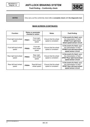
STOREDFRONT RIGHT-HAND WHEEL SPEED SENSOR CIRCUIT
CO.0: Open circuit or short circuit to earth
1.DEF: Magnetic/mechanical target fault
NOTESSpecial notes:
The fault is declared present during a road test at a vehicle speed > 6 mph (10 km/h).
Conditions for applying the fault finding procedure to stored faults:
Apply the fault finding procedure if the fault is present or stored.
Use the Wiring Diagrams Technical Note for KANGOO VLL.
CO.0
NOTESSpecial notes:
Command AC013 Wheel speed sensor supply test, must
be used only once.
Check the connection and the condition of the connections of the front right-hand wheel speed sensor, component
code 152. If the connector is faulty and there is a repair method (see Technical Note 6015A, Repairing electrical
wiring, Wiring: Precautions for repair), repair the connector, otherwise replace the wiring.
Disconnect the sensor, use command AC013 Wheel speed sensor supply test and check that pulses of voltage
of approximately 12 V are detected by a multimeter at the sensor connector terminals on the computer side.
Are the pulses present?
ABS8.1X76_V18_DF026
Page 23 of 57

38C-23
AFTER REPAIRClear the computer memory using command RZ001 Fault memory.
Carry out a road test followed by another check with the diagnostic tool.
V1 MR-376-X76-38C000$090.mif
ANTI-LOCK BRAKING SYSTEM
Fault finding – Interpretation of faults38C
ABS BOSCH 8.1
Vdiag No.: 18
DF026
CONTINUED 1
YES
If pulses are detected, the front right-hand wheel speed sensor is defective, replace
the sensor.
NOCheck the connection and condition of the connections of the ABS computer,
component code 118.
If the connector is faulty and there is a repair method (see Technical Note 6015A,
Repairing electrical wiring, Wiring: Precautions for repair), repair the connector,
otherwise replace the wiring.
Check and ensure the continuity of the following connections:
–4M between components 152 and 118,
–4N between components 152 and 118.
Also check the insulation between these two connections.
If the connection or connections are faulty and if there is a repair procedure (see
Technical Note 6015A, Electrical wiring repair, Wiring: Precautions for repair),
repair the wiring, otherwise replace it.
If the fault is still present, contact the Techline.
Page 24 of 57

38C-24
AFTER REPAIRClear the computer memory using command RZ001 Fault memory.
Carry out a road test followed by another check with the diagnostic tool.
V1 MR-376-X76-38C000$090.mif
ANTI-LOCK BRAKING SYSTEM
Fault finding – Interpretation of faults38C
ABS BOSCH 8.1
Vdiag No.: 18
DF026
CONTINUED 2
1.DEFNOTESNone.
Visually inspect the condition of the target and sensor (for dirt, metallic contamination, bearing grease, etc.), and
clean using compressed air if necessary.
If there is a lot of grease on the target, contact the Techline.
Check that the wheel speed sensor mounting is in good condition (correct clipping).
Check the conformity of the target (condition, number of teeth = 48 or 44 depending on the version) with the specific
command SC001 Check target teeth.
If the checks are correct:
– clear the computer fault memory using the command RZ001 Fault memory,
– exit fault finding mode, switch off the ignition and carry out a road test.
Replace the instrumented bearing if the fault recurs.
If the fault is still present, contact the Techline.