Page 182 of 340
180
Practical information
Repair procedure
1. SealingF Uncoil the white pipe G
fully.F
Unscrew the cap from the white pipe.F
Connect the white pipe to the valve of the
tyre to be repaired.
F
Connect the compressor's electric plug to
the vehicle's 12 V socket. F Star t the vehicle and leave the engine running.
Take care, this product is harmful (e.g.ethylene-glycol, colophony...) if swallowed and causes irritation to the eyes.Keep this product out of the reach of children.
Avoid removing any foreign bodieswhich have penetrated into the tyre.
Do not star t the compressor before connecting the white pipe to the tyre valve: the sealant product would be expelled through the pipe.
FSwitch off the ignition.
FTurn the selector Ato the "sealant"position.FCheck that the switch B
is in position "O".
Page 184 of 340

182
Practical information
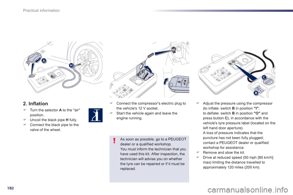
2. Infl ation F
Connect the compressor's electric plug to
the vehicle's 12 V socket.F Star t the vehicle again and leave the engine running.
F
Adjust the pressure using the compressor (to inflate: switch B
in position "I"
;
to deflate: switch B in position "O"and press button C ), in accordance with the
vehicle's tyre pressure label (located on the
left hand door aper ture).
A loss of pressure indicates that thepuncture has not been fully plugged; contact a PEUGEOT dealer or qualified
workshop for assistance.F Remove and stow the kit.F
Drive at reduced speed (50 mph [80 km/h] max) limiting the distance travelled toapproximately 120 miles (200 km).
As soon as possible, go to a PEUGEOTdealer or a qualified workshop.You must inform the technician that you have used this kit. After inspection, the technician will advise you on whether
the tyre can be repaired or if it must be replaced.
FTurn the selector Ato the "air" position.FUncoil the black pipe Hfully. FConnect the black pipe to the
valve of the wheel.
Page 185 of 340

8
183
Practical information
Removing the cartridge
F
Stow the black pipe. F
Detach the angled base from the white pipe.F
Suppor t the compressor ver tically.F
Unscrew the car tridge from the bottom.
Beware of discharges of fluid.
The expiry date of the fluid is indicated on the car tridge.
The sealant car tridge is designed for
single use; even if only partly used, itmust be replaced. After use, do not discard the car tridgeinto the environment, take it to an authorised waste disposal site or a PEUGEOT dealer.
Do not forget to obtain a new sealantcartridge, available from PEUGEOT dealers or from a qualified workshop.
Checking tyre pressures /
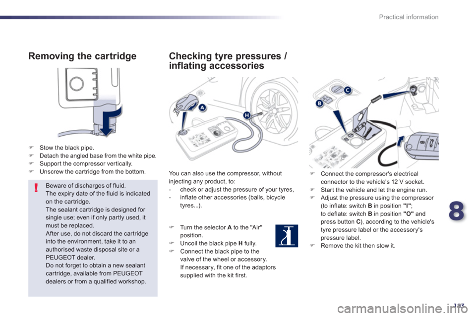
inflating accessories
You can also use the compressor, withoutinjecting any product, to:
- check or adjust the pressure of your tyres,
- inflate other accessories (balls, bicycle
tyres...).
FT
urn the selector Ato the "Air"
position.
FUncoil the black pipe
H
fully.FConnect the black pipe to the
valve of the wheel or accessory.
If necessar
y, fit one of the adaptorssupplied with the kit first.
F Connect the compressor's electrical connector to the vehicle's 12 V socket. F
Star t the vehicle and let the engine run. F
Adjust the pressure using the compressor (to inflate: switch B
in position "I"
;
to deflate: switch B in position "O"and press button C), according to the vehicle's
tyre pressure label or the accessory'spressure label. F Remove the kit then stow it.
Page 205 of 340
8
203
Practical information
Engine compartment
fuses
Fuse N°
Rating (A)Functions
F20 15
Front / rear screenwash pump.
F2
120 Headlamp wash pump.
F2215 Horn.
F2
315 Right-hand main beam headlamp.
F2
415 Left-hand main beam headlamp.
F27 5
Le
ft hand lamp mask.
F2
85 Right hand lamp mask. The fusebox is placed in the engine compartment near the battery.
Access to the fuses
F
Unclip the cover. F
Change the fuse (see corresponding paragraph).F
When you have finished, close the cover carefully to ensure correct sealing of thefusebox.
Page 207 of 340
8
205
Practical information
F Connect the red cable to the positive
terminal (+) of the flat battery A , then to the positive terminal (+) of the slave battery B
.
Starting using another
battery
F
Disconnect the battery from the vehicle, if necessary. F
Follow the instructions for use provided by
the manufacturer of the charger. F Reconnect starting with the negative
terminal (-). F Check that the terminals and connectors
are clean. If they are covered with sulphate (whitish or greenish deposit), remove themand clean them.
Charging the battery using
a battery charger
The Stop & Star t battery does not have to be disconnected for charging.
FConnect one end of the
green or black cable to the negative terminal (-) of theslave battery B.FConnect the other end of the green or blackcable to the ear th point C
on your vehicle (engine mounting).FOperate the star ter, let the engine run.
FWait until the engine returns to idle and
disconnect the cables.
Page 208 of 340

206
Practical information
The batteries contain harmful substancessuch as sulphuric acid and lead. They must be disposed of in accordance with regulations and must not, in anycircumstances, be discarded with household waste.
Take used remote control batteries andvehicle batteries to a special collection point.
Do not reverse the polarity and use only a 12 V charger.
Do not disconnect the terminals whilethe engine is running.
Do not charge the batteries without disconnecting the terminals first. Do not push the vehicle to star t the engine if it is fitted with the 6 -speed electronic gearbox system or an automatic gearbox.
It is advisable to disconnect the 12 Vbattery if the vehicle is to be left unusedfor more than one month.
Before disconnecting the battery
Wait 2 minutes after switching off the ignitionbefore disconnecting the 12 V battery.
Close the windows and the doors beforedisconnecting the battery.
Following reconnection of thebattery
Following reconnection of the 12 V battery,
switch on the ignition and wait 1 minute before
star ting to permit initialisation of the electronic
systems. However, if problems remain followingthis operation, contact a PEUGEOT dealer or a
qualified workshop.
Referring to the corresponding section, you
must yourself reinitialise:
- the remote control key,
- the panoramic sunroof blind,
- the GPS satellite navigation system.
Load reduction mode
System which manages the use of cer tain
functions according to the level of charge
remaining in the battery.
When the vehicle is bein
g driven, the load
reduction function temporarily deactivates certain functions, such as the air conditioning,
the heated rear screen...
The deactivated functions are reactivated
automatically as soon as conditions permit.
Page 209 of 340

8
207
Practical information
System which manages the duration of use of certain functions to conserve a sufficient level
of charge in the battery.
After the engine has stopped, you can still use functions such as the audio andtelematics system, windscreen wipers, dipped
beam headlamps, cour tesy lamps, etc. for a maximum combined duration of aboutforty minutes.
Energy economy mode
Switching to economy mode
A message then appears in the instrument panel screen indicating that the vehicle has
switched to economy mode and the active
functions are put on standby.
If a telephone call is being made at this time, it
will be maintained for around 10 minutes with
the Bluetooth hands-free system of your audio
system.
Exiting economy mode
These functions are reactivated automatically
next time the vehicle is driven.
F In order to resume the use of thesefunctions immediately, star t the engine and let it run:
- for less than ten minutes, to use
the equipment for approximatelyfive minutes,
- for more than ten minutes, to use the
equipment for up to approximatelythirty minutes.
Let the engine run for the duration specified toensure that the battery charge is sufficient.
Do not repeatedly and continuously restar t theengine in order to charge the battery.
A flat battery prevents the engine from star ting (refer to the "Battery" section).
Page 211 of 340
8
209
Practical information
Towing the vehicle
Procedure for having your vehicle towed or for towing another vehicle using a removable towing eye.
To w i ng from the front Access to the tools
The towing eye is installed in the boot under
the floor.
To gain access to it: F
open the boot, F
position the floor vertically,F
remove the towing eye.F
On the front bumper, unclip the cover by
pressing at the bottom.FScrew the towing eye in fully.FInstall the towing bar.FSwitch on the hazard warning lamps on the
towed vehicle.
F Place the gear lever in neutral (position Non the electronic gear control gearbox or automaticgearbox). Failure to obser ve this specialcondition could result in damage to cer tain braking components andthe absence of braking assistance the next time the engine is started.