2013 NISSAN TITAN fuel cap
[x] Cancel search: fuel capPage 3 of 26

TABLe Of cOnTenTS
NEW SYSTEM FEATURES
u SB/iPod® interface (if so equipped) .............................. 2
ESSENTIAL INFORMATION
Loose fuel cap . . . . . . . . . . . . . . . . . . . . . . . . . . . . . . . . . . . .\
. . . . . . . . . . . . 3
Tire Pressure Monitoring System (TPMS) ...........................3
Wide Open door (king cab models only) .......................... 4
FIRST D RIvE FEATURES
Remote k eyless entry System (if so equipped) ...................... 5
Opening the Tailgate ............................................ 5
Power Seat Adjustments (if so equipped) ...........................5
Automatic drive Positioner (if so equipped) ......................... 6
Outside Mirror control Switch (if so equipped) . . . . . . . . . . . . . . . . . . . . . . 6
Starting/Stopping the engine ..................................... 6
Headlight control Switch ........................................ 7
Windshield Wiper/Washer Switch ................................. 8
Automatic climate controls (if so equipped) ........................ 8
f M/AM/SiriusXM™ Satellite Radio with cd Player (if so equipped) .... 10
cruise control (if so equipped) .................................. 11
Power Outlets (if so equipped) .................................. 11
fuel-filler door ................................................ 12
S YSTEM GUIDE
Vehicle information display (if so equipped) ........................13
Bluetooth
® Hands-free Phone System (if so equipped) ...............13
System Operating Tips ...................................... 13
Bluetooth
® System without navigation (if so equipped) . . . . . . . . . . .14
Bluetooth® System with navigation (if so equipped) ..............15
navigation System (if so equipped) ...............................17
HomeLink
® universal Transceiver (if so equipped) ...................18
• A cellular telephone should not be used for any purpose while
driving so full attention may be given to vehicle operation.
• Always wear your seat belt.
• Supplemental air bags do not replace proper seat belt usage.
• Children 12 and under should always ride in the rear seat
properly secured in child restraints or seat belts according to
their age and weight.
• Do not drink and drive.
f or more information, refer to the “Safety –– Seats, seat belts and
supplemental restraint system (section 1)”, “Monitor, climate, audio,
phone and voice recognition systems (section 4)” and the “Starting
and driving (section 5)” of your Owner’s Manual.
Additional information about your vehicle is also available in your Owner’s Manual, navigation System Owner’s Manual and at www.nissanusa.com.
To view detailed
instructional videos, go to
www.nissanownersinfo.mobi/2013/titan or snap this barcode with an appropriate barcode reader.
Page 5 of 26

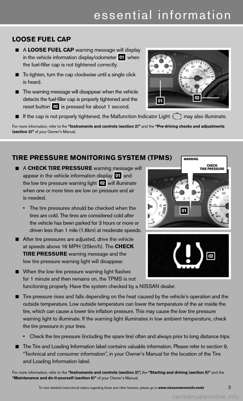
TIRE PRESSURE MONITORING SYSTEM (TPMS)
A ChEC k TIRE PRESSURE warning message will
appear in the vehicle information display
01 and
the low tire pressure warning light 02 will illuminate
when one or more tires are low on pressure and air
is needed.
• The tire pressures should be checked when the
tires are cold. The tires are considered cold after
the vehicle has been parked for 3 hours or more or
driven less than 1 mile (1.6km) at moderate speeds.
After tire pressures are adjusted, drive the vehicle
at speeds above 16 MPH (25km/h). The Ch ECk
TIRE PRESSURE warning message and the
low tire pressure warning light will disappear.
When the low tire pressure warning light flashes
for 1 minute and then remains on, the TPMS is not
functioning properly. Have the system checked by a ni SSAn dealer.
Tire pressure rises and falls depending on the heat caused by the vehicle’s operation and the
outside temperature. Low outside temperature can lower the temperature o\
f the air inside the
tire, which can cause a lower tire inflation pressure. This may cause the low tire pressure
warning light to illuminate. if the warning light illuminates in low ambient temperature, check
the tire pressure in your tires.
• Check the tire pressure (including the spare tire) often and always prior to long distance trips.
The Tire and Loading information label contains valuable information. Please refer to section 9,
“Technical and consumer information”, in your Owner’s Manual for the location of the Tire
and Loading information label.
for more information, refer to the “Instruments and controls (section 2)”, the “Starting and driving (section 5)” and the
“Maintenance and do-it-yourself (section 8)” of your Owner’s Manual.
LOOSE FUEL CAP
A LOOSE FUEL CAP warning message will display
in the vehicle information display/odometer
01 when
the fuel-filler cap is not tightened correctly.
To tighten, turn the cap clockwise until a single click
is heard.
The warning message will disappear when the vehicle
detects the fuel-filler cap is properly tightened and the
reset button
02 is pressed for about 1 second.
if the cap is not properly tightened, the Malfunction indicator Light may also illuminate.
f
or more information, refer to the “Instruments and controls (section 2)” and the “Pre-driving checks and adjustments
(section 3)” of your Owner’s Manual.
01
02
3
essential information
To view detailed in\fstructional videos\f regarding these a\fnd other features\f \fplease go to www.nissanownersin\hfo.mobi
0102
01
Page 16 of 26

12To view detailed in\fstructional videos\f regarding these a\fnd other features\f \fplease go to www.nissanownersin\hfo.mobi
FUEL-FILLER DOOR
The fuel-filler door is located on the driver’s side
of the vehicle.
To open the fuel-filler door, pull the lid open.
for more information, refer to the “Pre-driving checks and adjustments
(section 3)” of your Owner’s Manual.
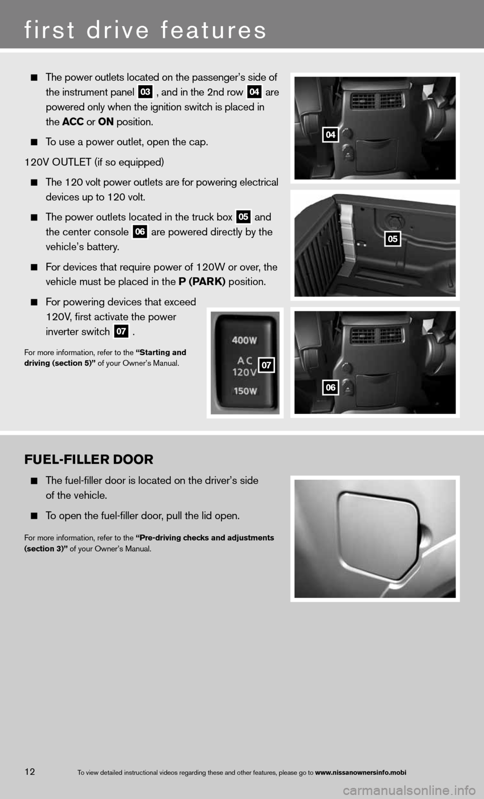
The power outlets located on the passenger’s side of
the instrument panel
03 , and in the 2nd row
04 are
powered only when the ignition switch is placed in
the ACC or ON position.
To use a power outlet, open the cap.
120V O uTLeT (if so equipped)
The 120 volt power outlets are for powering electrical
devices up to 120 volt.
The power outlets located in the truck box
05 and
the center console
06 are powered directly by the
vehicle’s battery.
f or devices that require power of 120W or over, the
vehicle must be placed in the P (PAR k) position.
For powering devices that exceed
120V, first activate the power
inverter switch
07 .
f
or more information, refer to the “Starting and
driving (section 5)” of your Owner’s Manual.
04
05
06
07
07
first drive features