2013 NISSAN QUEST ignition
[x] Cancel search: ignitionPage 2 of 36
*See your Owner’s Manual for information.
01
03
04
02
20
2122
23
05
08
06
13
24
151807
1619
17
12
25
11
24
14
09
10
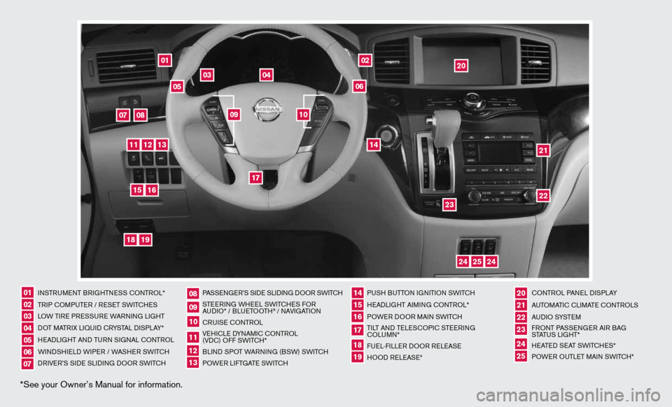
inSTR uM enT BR iGHTne SS cOnTROL*
TR iP c OMP uTeR / R eS eT SW iTc HeS
LOW T iRe PRe SSuRe WARnin G LiGHT
d OT MATR iX Li Quid c RYSTAL di SPLAY*
H eAd LiGHT And Tu Rn S iG nAL c OnTROL
W ind SHieL d W iPeR / WASHeR SW iT c H
dR iV e R’S Side SLidinG dOOR SWi TcH PASSenG
eR’S Side SLidinG dOOR SWi TcH
STee Rin G WH eeL SW iTc HeS fOR
A udi O* / BLueTOOTH
® / nAVi GATiOn
cR uiSe cOn TROL
Ve Hic Le d YnAM ic cOnTROL
(Vdc) O ff SWiTc H*
BLind SPOT WAR ninG (BSW) SWi TcH
POW eR LifTGATe SW iTc H PuSH B
uTTOn iGniTiOn SWi TcH
H eAd LiGHT Ai Min G c OnTROL*
POWe R dOOR MA in SWi TcH
Ti LT And Te LeSc OP ic STee Rin G
c OLu Mn*
fue L-fiLLe R dOOR R eLeAS e
HOO d ReLeAS e* cOn
TROL PA neL diSPLAY
A uTOMATic c LiMATe c OnTROLS
A u d i O SYST eM
f RO nT PASS enGeR Ai R BAG
STATu S LiGHT*
H eATed S eAT SWiTc HeS*
POW eR O uTLeT MAin SW iTc H*
0102030405
0910
2124
18
06
11
2225
07
141916
08
15
2023
17
1213
Page 4 of 36
arOu ND VI ew™ MONITOr (if so equipped)
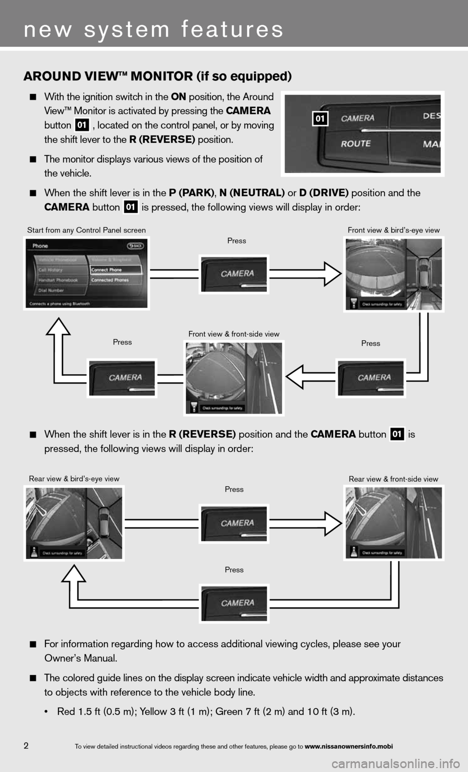
With the ignition switch in the ON position, the Around
View™ Monitor is activated by pressing the C aMera
button
01 , located on the control panel, or by moving
the shift lever to the r (reVer Se) position.
The monitor displays various views of the position of
the vehicle.
When the shift lever is in the P (P arK), N (N euTraL) or D (D rIVe) position and the
CaM era button
01 is pressed, the following views will display in order:
01
When the shift lever is in the r (reVer Se) position and the C aMera button
01 is
pressed, the following views will display in order:
Start from any control Panel screen
Rear view & bird’s-eye view front view & front-side view
Press
Press
Press
Press
Press
front view & bird’s-eye view
Rear view & front-side view
f or information regarding how to access additional viewing cycles, please\
see your
Owner’s Manual.
The colored guide lines on the display screen indicate vehicle width and \
approximate distances
to objects with reference to the vehicle body line.
• Red 1.5 ft (0.5 m); Yellow 3 ft (1 m); Green 7 ft (2 m) and 10 ft (3 m).
2
new system features
To view detailed in\fstructional videos\f regarding these a\fnd other features\f \fplease go to www.nissanownersin\Ifo.mobi
Page 7 of 36
TIre Pre SSure MONITOr ING SYSTeM (TPMS)
wITH eaSY FILL TI re aLerT
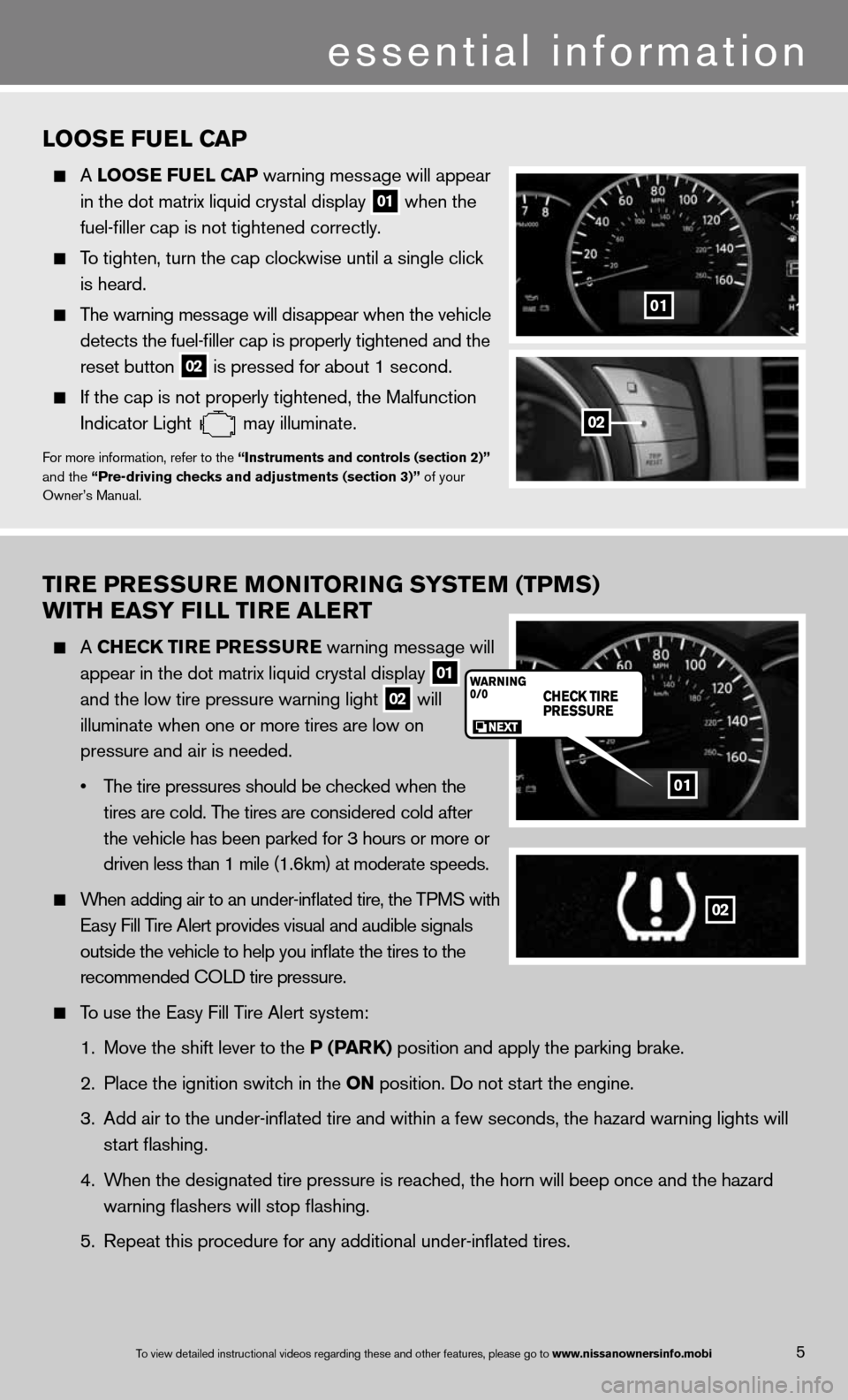
A CHe CK TIre P reSSure warning message will
appear in the dot matrix liquid crystal display
01
and the low tire pressure warning light
02 will
illuminate when one or more tires are low on
pressure and air is needed.
• The tire pressures should be checked when the
tires are cold. The tires are considered cold after
the vehicle has been parked for 3 hours or more or
driven less than 1 mile (1.6km) at moderate speeds.
When adding air to an under-inflated tire, the TPMS with
easy fill Tire Alert provides visual and audible signals
outside the vehicle to help you inflate the tires to the
recommended c OLd tire pressure.
To use the easy fill Tire Alert system:
1. Move the shift lever to the P (P arK) position and apply the parking brake.
2. Place the ignition switch in the ON position. do not start the engine.
3. Add air to the under-inflated tire and within a few seconds, the hazar\
d warning lights will
start flashing.
4. When the designated tire pressure is reached, the horn will beep once and the hazard
warning flashers will stop flashing.
5. Repeat this procedure for any additional under-inflated tires.
01
02
5To view detailed in\fstructional videos\f regarding these a\fnd other features\f \fplease go to www.nissanownersin\Ifo.mobi
LOOS e Fue L CaP
A LOOS e Fue L CaP warning message will appear
in the dot matrix liquid crystal display
01 when the
fuel-filler cap is not tightened correctly.
To tighten, turn the cap clockwise until a single click
is heard.
The warning message will disappear when the vehicle
detects the fuel-filler cap is properly tightened and the
reset button
02 is pressed for about 1 second.
if the cap is not properly tightened, the Malfunction
indicator Light
may illuminate.f
or more information, refer to the “Instruments and controls (section 2)”
and the “Pre-driving checks and adjustments (section 3)” of your
Owner’s Manual.
01
02
essential information
Page 9 of 36
01
03
04
05
06
02
NISSaN INTeLLIGeNT K eY® SYST eM
The ni SSAn intelligent k ey® System allows you to lock or
unlock your vehicle, open your liftgate and start the engine.
n OTe: it is important to make sure the intelligent k ey is
with you (that is, in your pocket or purse).
The operating range of the intelligent k ey is within
31.5 in (80 cm) from each request switch.
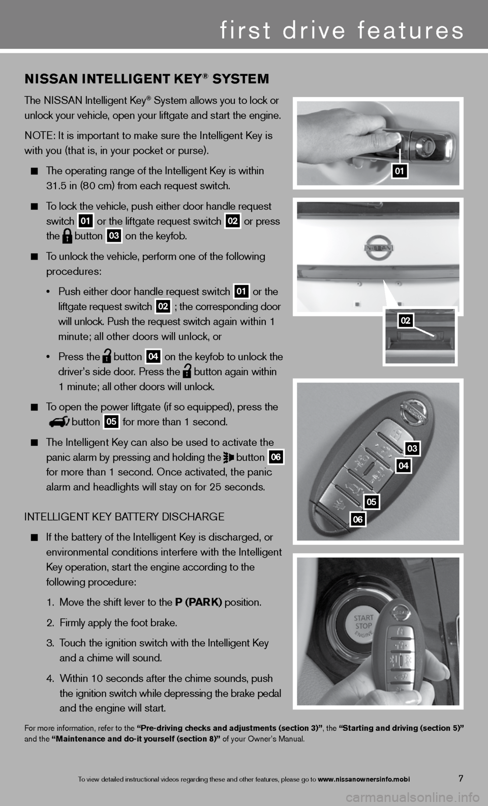
To lock the vehicle, push either door handle request
switch
01 or the liftgate request switch 02 or press
the
button 03 on the keyfob.
To unlock the vehicle, perform one of the following
procedures:
• Push either door handle request switch
01 or the
liftgate request switch 02 ; the corresponding door
will unlock. Push the request switch again within 1
minute; all other doors will unlock, or
• Press the
button 04 on the keyfob to unlock the
driver’s side door. Press the
button again within
1 minute; all other doors will unlock.
To open the power liftgate (if so equipped), press the
button 05 for more than 1 second.
The intelligent k ey can also be used to activate the
panic alarm by pressing and holding the
button 06
for more than 1 second. Once activated, the panic
alarm and headlights will stay on for 25 seconds.
inTe LLiGenT keY BATTe RY diSc HARG e
if the battery of the intelligent k ey is discharged, or
environmental conditions interfere with the intelligent
k ey operation, start the engine according to the
following procedure:
1. Move the shift lever to the P (Par K) position.
2. firmly apply the foot brake.
3. Touch the ignition switch with the intelligent k ey
and a chime will sound.
4. Within 10 seconds after the chime sounds, push
the ignition switch while depressing the brake pedal
and the engine will start.
for more information, refer to the “Pre-driving checks and adjustments (section 3)”, the “Starting and driving (section 5)”
and the “Maintenance and do-it yourself (section 8)” of your Owner’s Manual.
first drive features
7To view detailed in\fstructional videos\f regarding these a\fnd other features\f \fplease go to www.nissanownersin\Ifo.mobi
Page 13 of 36
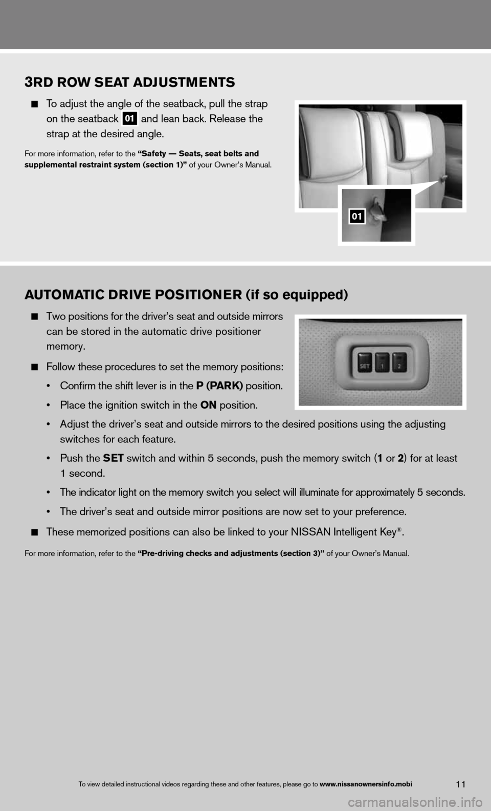
3rD r Ow S eaT aDJ uSTM eNTS
To adjust the angle of the seatback, pull the strap
on the seatback
01 and lean back. Release the
strap at the desired angle.
for more information, refer to the “Safety –– Seats, seat belts and
supplemental restraint system (section 1)” of your Owner’s Manual.
01
11To view detailed in\fstructional videos\f regarding these a\fnd other features\f \fplease go to www.nissanownersin\Ifo.mobi
auTOMa TIC DrIVe POSITION er (if so equipped)
Two positions for the driver’s seat and outside mirrors
can be stored in the automatic drive positioner
memory.
follow these procedures to set the memory positions:
• Confirm the shift lever is in the P (P arK) position.
• Place the ignition switch in the ON position.
• Adjust the driver’s seat and outside mirrors to the desired positions using the adjusting
switches for each feature.
• Push the S eT switch and within 5 seconds, push the memory switch (1 or 2) for at least
1 second.
• The indicator light on the memory switch you select will illuminate for approximately 5 seconds.
• The driver’s seat and outside mirror positions are now set to your preference.
These memorized positions can also be linked to your ni SSAn intelligent key®.
for more information, refer to the “Pre-driving checks and adjustments (section 3)” of your Owner’s Manual.
Page 14 of 36
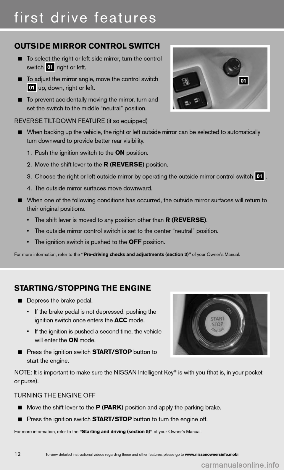
OuTSIDe MIrrOr CONTr OL SwITCH
To select the right or left side mirror , turn the control
switch
01 right or left.
To adjust the mirror angle, move the control switch
01 up, down, right or left.
To prevent accidentally moving the mirror, turn and
set the switch to the middle “neutral” position.
R eVe RSe Ti LT-d OWn feATu Re (if so equipped)
When backing up the vehicle, the right or left outside mirror can be selected to\
automatically
turn downward to provide better rear visibility.
1. Push the ignition switch to the ON position.
2. Move the shift lever to the r (reVer Se) position.
3. choose the right or left outside mirror by operating the outside mirror c\
ontrol switch
01 .
4. The outside mirror surfaces move downward.
When one of the following conditions has occurred, the outside mirror sur\
faces will return to
their original positions.
• The shift lever is moved to any position other than r (reVer Se).
• The outside mirror control switch is set to the center “neutral” position.
• The ignition switch is pushed to the OFF position.
for more information, refer to the “Pre-driving checks and adjustments (section 3)” of your Owner’s Manual.
01
ST arTING/STOPPING TH e eNGIN e
depress the brake pedal.
• If the \brake pedal i\fs not depressed\f pu\fshing the
ignition switch on\fce enters the ACC mode.
• If the ignition is \fpushed a second ti\fme\f the vehicle
will enter the ON mode.
Press the ignition switch ST arT/STOP button to
start the engine.
n OTe: it is important to make sure the ni SSAn intelligent key
® is with you (that is, in your pocket
or purse).
T uRnin G THe enGine Off
Move the shift lever to the P (P arK) position and apply the parking brake.
Press the ignition switch ST arT/STOP button to turn the engine off.
for more information, refer to the “Starting and driving (section 5)” of your Owner’s Manual.
12
first drive features
To view detailed in\fstructional videos\f regarding these a\fnd other features\f \fplease go to www.nissanownersin\Ifo.mobi
Page 15 of 36
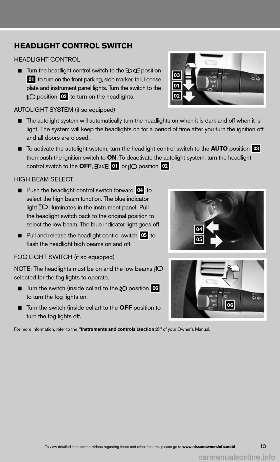
HeaDLIGHT CONTr OL SwITCH
HeAd LiGHT c OnTROL
Turn the headlight control switch to the
position
01 to turn on the front parking, side marker, tail, license
plate and instrument panel lights. Turn the switch to the
position
02 to turn on the headlights.
A uTOLi GHT SYSTe M (if so equipped)
The autolight system will automatically turn the headlights on when it is\
dark and off when it is
light. The system will keep the headlights on for a period of time after you tur\
n the ignition off
and all doors are closed.
To activate the autolight system, turn the headlight control switch to the au TO position
03
then push the ignition switch to ON. To deactivate the autolight system, turn the headlight
control switch to the OFF,
01 or
position
02 .
H iGH B eAM S eLec T
Push the headlight control switch forward
04 to
select the high beam function. The blue indicator
light
illuminates in the instrument panel. Pull
the headlight switch back to the original position to
select the low beam. The blue indicator light goes off.
Pull and release the headlight control switch
05 to
flash the headlight high beams on and off.
fOG Li GHT SW iTc H (if so equipped)
n OTe: The headlights must be on and the low beams
selected for the fog lights to operate.
Turn the switch (inside collar) to the position
06
to turn the fog lights on.
Turn the switch (inside collar)
to the OFF position to
turn the fog lights off.
for more information, refer to the “Instruments and controls (section 2)” of your Owner’s Manual.
01
04
03
02
05
06
13To view detailed in\fstructional videos\f regarding these a\fnd other features\f \fplease go to www.nissanownersin\Ifo.mobi