2013 NISSAN GT-R display
[x] Cancel search: displayPage 192 of 346
4 Display screen, heater, air conditionerand audio systems
Multi function display Owner’s Manual .............................. 4-2
Page 193 of 346
4-2Display screen, heater, air conditioner and audio systems
Refer to the separate Multi Function Display
Owner’s Manual that includes the following
information.
.Multi function display system
. Navigation
. Audio system
. Bluetooth
®hands-free phone system
. Heater and air conditioner
. Viewing information
. Other settings
. Voice recognition
. Monitor system
. Multi function meter
. General system information
MULTI FUNCTION DISPLAY
OWNER’S MANUAL
Page 194 of 346
5 Starting and driving
Precautions when starting and driving ............................... 5-3Exhaust gas (carbon monoxide) ..................................... 5-3Three-way catalyst ............................................................. 5-3
Tire Pressure Monitoring System (TPMS) ................... 5-4
Avoiding collision and rollover ........................................ 5-7
Off-road recovery ............................................................... 5-7
Rapid air pressure loss ..................................................... 5-8
Drinking alcohol/drugs and driving ................................ 5-8All-Wheel Drive (AWD) driving safety precautions .... 5-9
Push-button ignition switch ................................................... 5-9
Operating range for engine start ................................ 5-10
Ignition switch operation ............................................... 5-10
Ignition switch positions ................................................ 5-10
Emergency engine shut off ........................................... 5-11
Intelligent Key battery discharge ................................. 5-11
Before starting the engine .................................................. 5-13
Starting the engine ............................................................... 5-13
Driving the vehicle ................................................................ 5-15 Dual clutch transmission ............................................... 5-15
Driving tips ........................................................................\
5-21
VDC, transmission and suspension setup switches .... 5-24 How to switch the modes ............................................ 5-25
Features of each mode .................................................. 5-27 Turbocharger system ........................................................... 5-31
R mode start function ......................................................... 5-32
How to use R mode start function ........................... 5-33
Parking brake ........................................................................\
. 5-33
Cruise control ........................................................................\
5-34 Precautions on cruise control .................................... 5-35
Steering-wheel-mounted controls ............................ 5-35
Indicators and display .................................................. 5-36
Cruise control operations ........................................... 5-36
Hill Start Assist ..................................................................... 5-38
Break-in schedule ................................................................ 5-39 Wheel alignment ........................................................... 5-39
Increasing fuel economy ..................................................... 5-40
All-Wheel Drive (AWD) ...................................................... 5-41 AWD warning light ....................................................... 5-41
Tight corner braking phenomenon ........................... 5-42
Tires ........................................................................\
.......... 5-43AWD system characteristics ...................................... 5-43
Limited Slip Differential (LSD) .......................................... 5-44
Parking/parking on hills ....................................................... 5-45
Power steering ...................................................................... 5-46
Brake system ........................................................................\
. 5-47 Braking precautions ..................................................... 5-47
Parking brake break-in ................................................. 5-47
Page 198 of 346
Your vehicle has also been equipped with a
TPMS malfunction indicator to indicate when the
system is not operating properly. The TPMS
malfunction indicator is combined with the low
tire pressure telltale. When the system detects a
malfunction, the telltale will flash for approxi-
mately one minute and then remain continuously
illuminated. This sequence will continue upon
subsequent vehicle start-ups as long as the
malfunction exists. When the malfunction indi-
cator is illuminated, the system may not be able
to detect or signal low tire pressure as intended.
TPMS malfunctions may occur for a variety of
reasons, including the installation of replace-
ment or alternate tires or wheels on the vehicle
that prevent the TPMS from functioning properly.
Always check the TPMS malfunction telltale
after replacing one or more tires or wheels on
your vehicle to ensure that the replacement or
alternate tires and wheels allow the TPMS to
continue to function properly.Additional information
.The TPMS will activate only when the
vehicle is driven at speeds above 16 MPH
(25 km/h) . Also, this system may not detect
a sudden drop in tire pressure (for example a
flat tire while driving) .
. The low tire pressure warning light does not
automatically turn off when the tire pressure
is adjusted. After the tire is inflated to the
recommended pressure, the vehicle must be
driven at speeds above 16 MPH (25 km/h)
to activate the TPMS and turn off the low tire
pressure warning light. Use a tire pressure
gauge to check the tire pressure.
. Tire pressure rises and falls depending on
the heat caused by the vehicle’s operation
and the outside temperature. Low outside
temperature can lower the temperature of
the air inside the tire which can cause a
lower tire inflation pressure. Altitude can
also affect tire pressure. These may cause
the low tire pressure warning light to
illuminate. If the warning light illuminates,
check the tire pressure for all four tires.
. GT-R vehicles are delivered from the factory
with nitrogen-filled tires. For best perfor-
mance, NISSAN recommends that GT-R
owners maintain their vehicles by using nitrogen for tire inflation. Because nitrogen
is more stable than compressed air, it is less
prone to pressure fluctuation resulting from
temperature variations. If nitrogen is not
available, compressed air may be safely
used under normal driving conditions. How-
ever, NISSAN recommends refilling with
Nitrogen for maximum tire performance.
. The Tire and Loading Information label (also
referred to as the vehicle placard or tire
inflation pressure label) is located in the
driver’s door opening.
. You can also check the pressure of all tires
on the multi function display. Refer to the
separate Multi Function Display Owner’s
Manual.
. The tire pressure sensor should be reset
anytime the wheels or tires are removed or
replaced.
. If the tire is removed in order to replace the
tire pressure sensor battery, it may not be
possible to reuse the removed tire from the
wheel. To replace the tire pressure sensor
battery, contact a GT-R certified NISSAN
dealer.
Starting and driving5-5
Page 199 of 346
5-6Starting and driving
WARNING
.If the low tire pressure warning light
illuminates or LOW PRESSURE in-
formation is displayed on the moni-
tor screen while driving, avoid
sudden steering maneuvers or
abrupt braking, reduce vehicle
speed, pull off the road to a safe
location and stop the vehicle as
soon as possible. Driving with un-
der-inflated tires may permanently
damage the tires and increase the
likelihood of tire failure. Serious
vehicle damage could occur and
may lead to an accident and could
result in serious personal injury.
Check the tire pressure for all four
tires. Adjust the tire pressure to the
recommended COLD tire pressure
shown on the Tire and Loading
Information label to turn the low
tire pressure warning light off. If the
light still illuminates while driving
after adjusting the tire pressure, a
tire may be flat.
. Although you can continue driving
with a punctured run-flat tire, re-
member that vehicle handling sta- bility is reduced, which could lead to
an accident and personal injury.
Also, driving a long distance at high
speeds may damage the tires.
. Do not drive at speeds above 50
MPH (80 km/h) and do not drive
more than 50 miles (80 km) with a
punctured run-flat tire. The actual
distance the vehicle can be driven
on a flat tire depends on outside
temperature, vehicle load, road con-
ditions and other factors.
. When a wheel is replaced, the TPMS
will not function and the low tire
pressure warning light will flash for
approximately 1 minute. The light
will remain on after 1 minute. Con-
tact your GT-R certified NISSAN
dealer as soon as possible for tire
replacement and/or system reset-
ting.
. Replacing tires with those not ori-
ginally specified by NISSAN could
affect the proper operation of the
TPMS.
. Do not inject any tire liquid or
aerosol tire sealant into the tires,
as this may cause a malfunction of the tire pressure sensors.NOTICE
.
The TPMS may not function properly
when the wheels are equipped with
tire chains or the wheels are buried
in snow.
. The TPMS may not function properly
if the TPMS sensor is not reset and
when wheels/tires from another
GT-R are installed on your vehicle.
. The TPMS will not function properly
if non-GT-R specified wheels are
installed on the vehicle.
. Do not place metalized film or any
metal parts (antenna, etc.) on the
windows. This may cause poor re-
ception of the signals from the tire
pressure sensors, and the TPMS will
not function properly.
Some devices and transmitters may temporarily
interfere with the operation of the TPMS and
cause the low tire pressure warning light to
illuminate. Some examples are:
. Facilities or electric devices using similar
Page 204 of 346
NOTE:
.If the steering lock release malfunction
indicator appears on the vehicle infor-
mation display when the ignition
switch is pressed, press the ignition
switch again while gently turning the
steering wheel left and right.
(
“Steering lock release malfunc-
tion indicator” page 2-42)
. If the shift
&Pwarning appears on the
vehicle information display when the
ignition switch is pushed, the shift lever
is in any position except the
&Pposi-
tion. Move the shift lever to the&Pposition. (“Shift “P” warning”
page 2-42)
. If the Intelligent Key battery discharge
indicator appears on the vehicle infor-
mation display, the Intelligent Key
battery is discharged and the ignition
switch will not operate. Insert the
Intelligent Key into the key port to
operate the ignition switch.
(
“Intelligent Key battery discharge
indicator” page 2-43)
. When all of the following conditions
are met for 60 minutes, the battery
saver system will cut off the power
supply to prevent battery discharge. —
The ignition switch is in the ACC
position, and
— All doors are closed, and
— The shift lever is in the
&Pposition.
. Do not leave the vehicle with the
ignition switch in the ACC or ON
position when the engine is not run-
ning for an extended period of time.
This can discharge the battery.
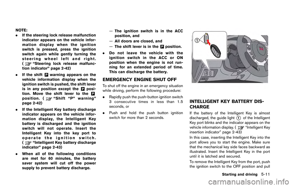
EMERGENCY ENGINE SHUT OFF
To shut off the engine in an emergency situation
while driving, perform the following procedure:
.Rapidly push the push-button ignition switch
3 consecutive times in less than 1.5
seconds, or
. Push and hold the push button ignition
switch for more than 2 seconds.
INTELLIGENT KEY BATTERY DIS-
CHARGE
If the battery of the Intelligent Key is almost
discharged, the guide light
*1of the Intelligent
Key port blinks and the indicator appears on the
vehicle information display. (
“Intelligent Key
insertion indicator” page 2-43)
In this case, inserting the Intelligent Key into the
port allows you to start the engine. Make sure
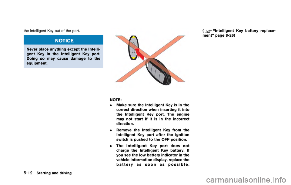
that the mechanical key side faces backward as
illustrated. Insert the Intelligent Key in the port
until it is latched and secured.
To remove the Intelligent Key from the port, push
the ignition switch to the OFF position and pull
Starting and driving5-11
Page 205 of 346
5-12Starting and driving
the Intelligent Key out of the port.
NOTICE
Never place anything except the Intelli-
gent Key in the Intelligent Key port.
Doing so may cause damage to the
equipment.
NOTE:
.Make sure the Intelligent Key is in the
correct direction when inserting it into
the Intelligent Key port. The engine
may not start if it is in the incorrect
direction.
. Remove the Intelligent Key from the
Intelligent Key port after the ignition
switch is pushed to the OFF position.
. The Intelligent Key port does not
charge the Intelligent Key battery. If
you see the low battery indicator in the
vehicle information display, replace the
battery as soon as possible. (
“Intelligent Key battery replace-
ment” page 8-26)
Page 207 of 346
5-14Starting and driving
NOTE:
.If the engine is difficult to start, de-
press the accelerator pedal all the way
to the floor and hold it. Push the
ignition switch with the brake pedal
depressed to start cranking the engine.
After 5 or 6 seconds, stop cranking by
pushing the ignition switch to the OFF
position, and then release the accel-
erator pedal. Then perform steps 1 to 5
to start the engine. If the engine starts,
but fails to run, repeat this procedure.
. Starting and stopping the engine over a
short period of time may make the
vehicle more difficult to start. If this
occurs, wait for more than 3 minutes,
and then push the ignition switch again
to start the engine.
. To maintain high performance over a
long period of time, the engine speed is
limited to 5,000 rpm when the engine is
revved with the shift lever in the
&Nor
&Pposition, and to 4,000 rpm when the
engine oil or coolant temperature is
low or higher than normal.
. If the ignition switch is pushed before
the shift lever is moved to the
&Pposition, the ignition switch will not change to the OFF position. If this
occurs, the SHIFT
&Pwarning display
appears on the vehicle information
display. When stopping the engine, be
sure to move the shift lever to the
&Pposition and then push the ignition
switch. Failure to do so may result in
discharge of the battery. (
“Shift
“P” warning” page 2-42)
. If the shift lever was in the
&A↔&Mor&Rposition when the engine was stopped,
then be sure to move the shift lever to
the
&Pposition before starting the
engine the next time. If the engine is
started with the shift lever in the
&Nposition, then it may not be possible to
drive the vehicle even when the shift
lever is moved to the
&A↔&Mor&Rposition. If this occurs, the SHIFT&Pwarning appears on the vehicle infor-
mation display. (“Shift “P” warn-
ing” page 2-42)
CAUTION
If the engine was stopped soon when
the engine is hot, the cooling fan may
operate for approximately 2 minutes
after the engine was stopped to cool the components in the engine compart-
ment. When the cooling fan is operat-
ing, be sure that hands or other items
do not get caught in it.