Page 99 of 346
2-4Instruments and controls
1. Outside mirror control switch (P.3-28)
2. Center dial*
3. Audio system*
4. Heater and air conditioner*
5. Multi function display*
6. Hazard warning flasher switch (P.2-52)7. Glove box (P.2-57)
8. Fuse box cover (P.8-23)
9. Power outlet (P.2-54)
10. Rear window defroster switch (P.2-48)
11. Front passenger air bag status light (P.1-38)
12. Compact Disc slot*13. Trunk release power cancel switch (P.3-21)
*: Refer to the separate Multi Function Display
Owner’s Manual.
INSTRUMENT PANEL
Page 100 of 346
1. Trip A/B reset switch (P.2-6)
2. Speedometer (P.2-6)
3. Tachometer (P.2-7)/Upshift indicator (P.2-9)
4. Transmission position indicator (P.2-8)
5. Engine coolant temperature gauge (P.2-7)
6. ENTER switch (P.2-14)7. Instrument brightness control switch (P.2-11)
8. Vehicle information display (P.2-11)
9. Odometer/twin trip odometer (P.2-6)
10. Fuel gauge (P.2-8)
11. NEXT switch (P.2-14)
NOTE:
.
Meters and gauges will illuminate
when the ignition switch is pushed to
the ON position.
. The needle indicators may move
slightly after the ignition switch is
pushed to the OFF position. This does
not indicate that there is a malfunction.
Instruments and controls2-5
METERS AND GAUGES
Page 101 of 346
2-6Instruments and controls
SPEEDOMETER
The speedometer indicates the vehicle speed.
ODOMETER/TWIN TRIP OD-
OMETER
The odometer*1indicates the total distance
that the vehicle has been driven.
The twin trip odometer
*2indicates the
distance of individual trips.
Changing the display
Push the TRIP A/B RESET switch to change
between trips&Aand&B.
Resetting the trip odometer
To reset a trip, display the trip that you want to
reset to zero, then push and hold the TRIP A/B RESET switch for more than 1 second.
NOTE:
When the battery is disconnected, the
memory for trips
&Aand&Bis erased,
and both return to zero.
Page 103 of 346

2-8Instruments and controls
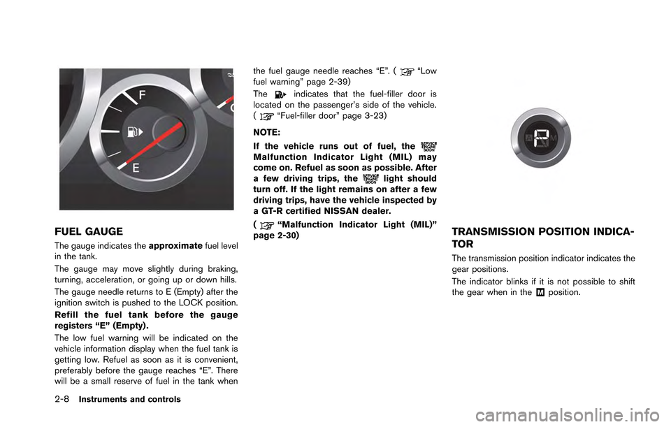
FUEL GAUGE
The gauge indicates theapproximatefuel level
in the tank.
The gauge may move slightly during braking,
turning, acceleration, or going up or down hills.
The gauge needle returns to E (Empty) after the
ignition switch is pushed to the LOCK position.
Refill the fuel tank before the gauge
registers “E” (Empty) .
The low fuel warning will be indicated on the
vehicle information display when the fuel tank is
getting low. Refuel as soon as it is convenient,
preferably before the gauge reaches “E”. There
will be a small reserve of fuel in the tank when the fuel gauge needle reaches “E”. (
“Low
fuel warning” page 2-39)
The
indicates that the fuel-filler door is
located on the passenger’s side of the vehicle.
(
“Fuel-filler door” page 3-23)
NOTE:
If the vehicle runs out of fuel, the
Malfunction Indicator Light (MIL) may
come on. Refuel as soon as possible. After
a few driving trips, the
light should
turn off. If the light remains on after a few
driving trips, have the vehicle inspected by
a GT-R certified NISSAN dealer.
(
“Malfunction Indicator Light (MIL)”
page 2-30)TRANSMISSION POSITION INDICA-
TOR
The transmission position indicator indicates the
gear positions.
The indicator blinks if it is not possible to shift
the gear when in the
&Mposition.
Page 104 of 346
1. Upshift indicator (green)
2. Upshift indicator (yellow)
3. Upshift indicator (red)
UPSHIFT INDICATOR
When the upshift indicator is set to on, the
indicators on the tachometer will illuminate to
help upshift at a constant engine speed from any
gear or to warn the driver of over-revving.
The upshift indicator operates only when the
shift lever is in the
&Mposition. This function
consists of two modes that can be selected on
the vehicle information display: AUTO setting
and MANUAL setting.
Instruments and controls2-9
Page 105 of 346

2-10Instruments and controls
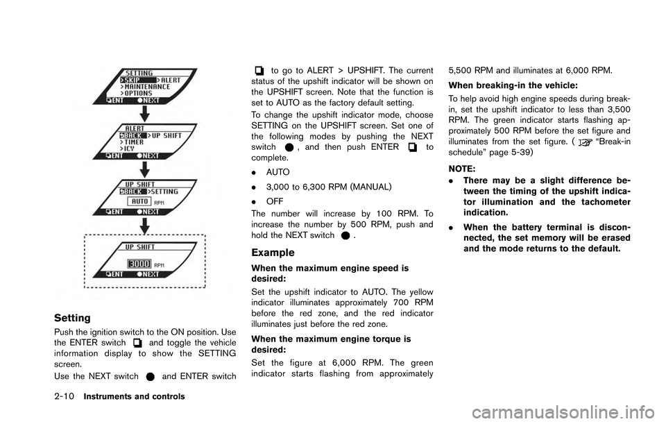
Setting
Push the ignition switch to the ON position. Use
the ENTER switchand toggle the vehicle
information display to show the SETTING
screen.
Use the NEXT switch
and ENTER switch
to go to ALERT > UPSHIFT. The current
status of the upshift indicator will be shown on
the UPSHIFT screen. Note that the function is
set to AUTO as the factory default setting.
To change the upshift indicator mode, choose
SETTING on the UPSHIFT screen. Set one of
the following modes by pushing the NEXT
switch
, and then push ENTERto
complete.
. AUTO
. 3,000 to 6,300 RPM (MANUAL)
. OFF
The number will increase by 100 RPM. To
increase the number by 500 RPM, push and
hold the NEXT switch
.
Example
When the maximum engine speed is
desired:
Set the upshift indicator to AUTO. The yellow
indicator illuminates approximately 700 RPM
before the red zone, and the red indicator
illuminates just before the red zone.
When the maximum engine torque is
desired:
Set the figure at 6,000 RPM. The green
indicator starts flashing from approximately 5,500 RPM and illuminates at 6,000 RPM.
When breaking-in the vehicle:
To help avoid high engine speeds during break-
in, set the upshift indicator to less than 3,500
RPM. The green indicator starts flashing ap-
proximately 500 RPM before the set figure and
illuminates from the set figure. (
“Break-in
schedule” page 5-39)
NOTE:
. There may be a slight difference be-
tween the timing of the upshift indica-
tor illumination and the tachometer
indication.
. When the battery terminal is discon-
nected, the set memory will be erased
and the mode returns to the default.
Page 106 of 346

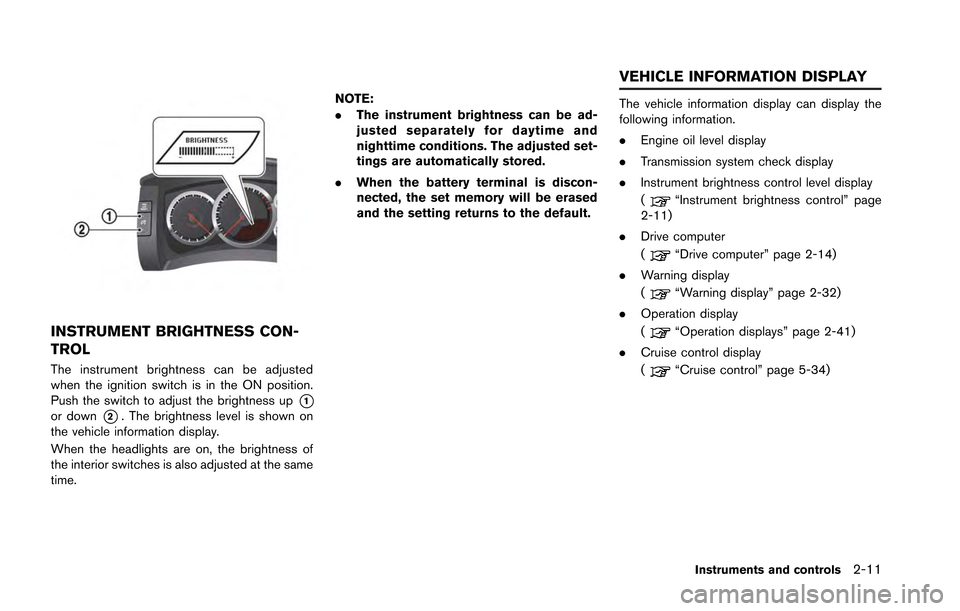
INSTRUMENT BRIGHTNESS CON-
TROL
The instrument brightness can be adjusted
when the ignition switch is in the ON position.
Push the switch to adjust the brightness up
*1or down*2. The brightness level is shown on
the vehicle information display.
When the headlights are on, the brightness of
the interior switches is also adjusted at the same
time. NOTE:
.
The instrument brightness can be ad-
justed separately for daytime and
nighttime conditions. The adjusted set-
tings are automatically stored.
. When the battery terminal is discon-
nected, the set memory will be erased
and the setting returns to the default.
The vehicle information display can display the
following information.
.Engine oil level display
. Transmission system check display
. Instrument brightness control level display
(
“Instrument brightness control” page
2-11)
. Drive computer
(
“Drive computer” page 2-14)
. Warning display
(
“Warning display” page 2-32)
. Operation display
(
“Operation displays” page 2-41)
. Cruise control display
(
“Cruise control” page 5-34)
Instruments and controls2-11
VEHICLE INFORMATION DISPLAY
Page 107 of 346
2-12Instruments and controls
ENGINE OIL LEVEL DISPLAY
When the ignition switch is pushed to the ON
position, the engine oil status before starting the
engine is indicated as illustrated.
When the oil level is normal
“OIL LEVEL OK” is displayed. Push the dis-
played LEVEL switchto check the oil level.
NOTE:
The engine oil level can be displayed after
the “OIL LEVEL OK” display turns off or
while the engine is started and running.
(
“Maintenance” page 2-20)
When the oil level is low
If the message shown above is displayed, the
engine oil level is low.
Warm up the engine in a level location. After at
least 5 minutes have passed since engine stop,
use the engine oil dipstick to check the oil level.
(
“Engine oil” page 8-12)
If the oil level is low, have additional engine oil
added, or the oil changed, at a GT-R certified
NISSAN dealer.