Page 260 of 706
Features and controls
3-167
3
NOTE�To avoid the risk of damage to the tire inflation pressure
sensors, have any punctured tire repaired by an authorized
Mitsubishi Motors dealer. If the tire repair is not done by
an authorized Mitsubishi Motors dealer, it is not covered
by your warranty.
�Do not use an aerosol puncture-repair product on any tire.
Such a spray could damage the tire inflation pressure sen-
sors. Have any puncture repaired by an authorized Mit-
subishi Motors dealer.The tire pressure monitoring system may not work normally in
the following circumstances:
�A wireless facility or device using the same frequency is
near the vehicle.
�Snow or ice is stuck inside the fenders and/or on the
wheels.
�The tire inflation pressure sensor’s battery is dead.
�Wheels other than Mitsubishi genuine wheels are being
used.
�Wheels that are not fitted with tire inflation pressure sen-
sors are being used.
�Wheels whose ID codes are not memorized by the vehicle
are used.
�Compact spare tire is fitted on a road wheel.
�A window tint that affects the radio wave signals is
installed.
NOTE�Tire inflation pressures vary with the ambient tempera-
ture. If the vehicle is subjected to large variations in ambi-
ent temperature, the tire inflation pressures may be under-
inflated (causing the warning light/display to come on)
when the ambient temperature is relatively low. If the
warning light/display comes on, adjust the tire inflation
pressure.
WA R N I N G
!�If the warning light/display illuminates while you
are driving, avoid hard braking, sharp steering
maneuvers and high speeds. Driving with an under-
inflated tire adversely affects vehicle performance
and can result in an accident.
CAUTION
!�If a tire has a puncture, replace that tire with the
spare tire. Driving on a punctured tire could lead to
an accident.�The warning light/display may not illuminate imme-
diately in the event of a tire blowout or rapid leak.
BK0151000US.book 167 ページ 2012年3月29日 木曜日 午後6時8分
Page 261 of 706
3-168 Features and controls
3
Whenever the tires and wheels are replaced with
new ones
N00532900179
If new wheels with new tire inflation pressure sensors are
installed, their ID codes must be programmed into the tire pres-
sure monitoring system. Have tire and wheel replacement per-
formed by an authorized Mitsubishi Motors dealer to avoid the
risk of damaging the tire inflation pressure sensors. If the
wheel replacement is not done by an authorized Mitsubishi
Motors dealer, it is not covered by your warranty.
General information
N00533000177
Your tire pressure monitoring system operates on a radio fre-
quency subject to Federal Communications Commission
(FCC) Rules (For vehicles sold in U.S.A.) and Industry Canada
Rules (For vehicles sold in Canada). This device complies with
Part 15 of the FCC Rules and RSS-Gen of the Industry Canada
Rules.
Operation is subject to the following two conditions.
�This device may not cause harmful interference.
�This device must accept any interference received, includ-
ing interference that may cause undesired operation.
CAUTION
!�The use of non-genuine wheels will prevent the
proper fit of the tire inflation pressure sensors,
resulting in air leakage or damage to the sensors.
CAUTION
!�Changes or modifications not expressly approved by
the manufacturer for compliance could void the
user’s authority to operate the equipment.
BK0151000US.book 168 ページ 2012年3月29日 木曜日 午後6時8分
Page 263 of 706
3-170 Features and controls
3
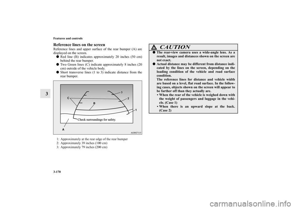
Reference lines on the screenReference lines and upper surface of the rear bumper (A) are
displayed on the screen.
�Red line (B) indicates approximately 20 inches (50 cm)
behind the rear bumper.
�Two Green lines (C) indicate approximately 8 inches (20
cm) outside of the vehicle body.
�Short transverse lines (1 to 3) indicate distance from the
rear bumper.1: Approximately at the rear edge of the rear bumper
2: Approximately 39 inches (100 cm)
3: Approximately 79 inches (200 cm)
CAUTION
!�The rear-view camera uses a wide-angle lens. As a
result, images and distances shown on the screen are
not exact.�Actual distance may be different from distance indi-
cated by the lines on the screen, depending on the
loading condition of the vehicle and road surface
condition.
The reference lines for distance and vehicle width
are based on a level, flat road surface. In the follow-
ing cases, objects shown on the screen will appear to
be farther off than they actually are.
• When the rear of the vehicle is weighed down with
the weight of passengers and luggage in the vehi-
cle. (Case 1)
• When there is an upward slope at the back.
(Case 2)
BK0151000US.book 170 ページ 2012年3月29日 木曜日 午後6時8分
Page 266 of 706
Features and controls
3-173
3
To permanently set the non-display mode1. Turn the ignition switch to the “ON” position.
2. Put the gearshift lever or the selector lever in the “R”
(REVERSE) position.
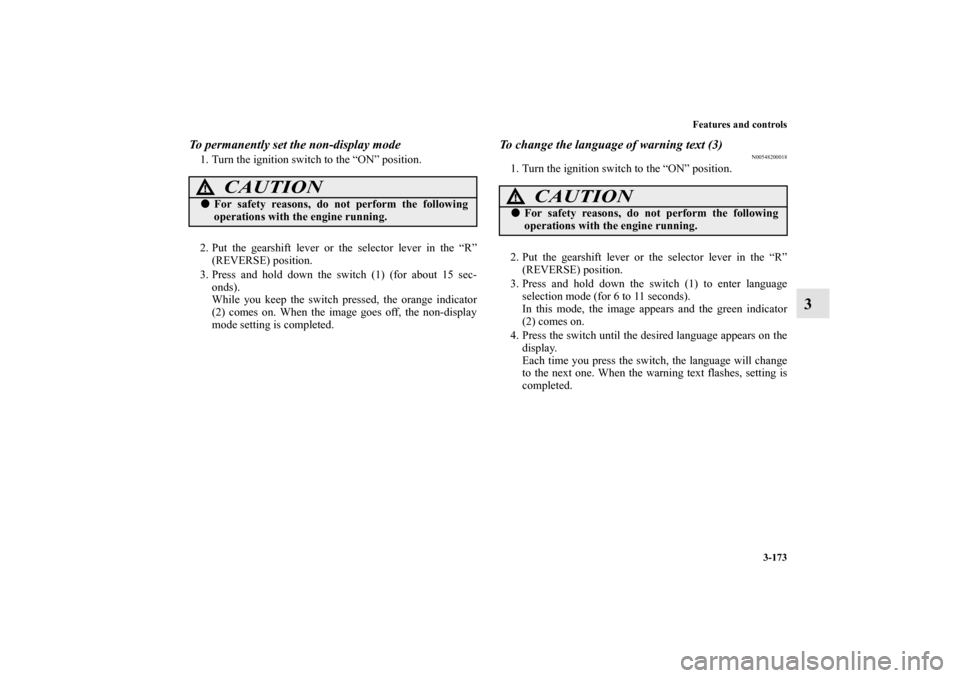
3. Press and hold down the switch (1) (for about 15 sec-
onds).
While you keep the switch pressed, the orange indicator
(2) comes on. When the image goes off, the non-display
mode setting is completed.
To change the language of warning text (3)
N00548200018
1. Turn the ignition switch to the “ON” position.
2. Put the gearshift lever or the selector lever in the “R”
(REVERSE) position.
3. Press and hold down the switch (1) to enter language
selection mode (for 6 to 11 seconds).
In this mode, the image appears and the green indicator
(2) comes on.
4. Press the switch until the desired language appears on the
display.
Each time you press the switch, the language will change
to the next one. When the warning text flashes, setting is
completed.
CAUTION
!�For safety reasons, do not perform the following
operations with the engine running.
CAUTION
!�For safety reasons, do not perform the following
operations with the engine running.
BK0151000US.book 173 ページ 2012年3月29日 木曜日 午後6時8分
Page 268 of 706
Features and controls
3-175
3
Ta c h o m e t e r
N00519200247
The tachometer shows engine revolutions per minute. This
allows the driver to determine the most efficient shift position
(manual transaxle), selector position {continuously variable
transmission (CVT)} or shift position (Twin Clutch SST) and
engine speed combinations.
This gauge also assists in evaluating engine performance.
Ty p e 2
CAUTION
!�The red zone indicates an engine speed beyond the
range of safe operation.�Select the correct shift position (manual transaxle),
selector position (CVT) or gearshift position (Twin
Clutch SST) to control the engine speed so that the
tachometer indicator does not enter the red zone.
BK0151000US.book 175 ページ 2012年3月29日 木曜日 午後6時8分
Page 272 of 706
Features and controls
3-179
3
warning display screen (With ignition switch
in the “OFF” position)
N00555200212
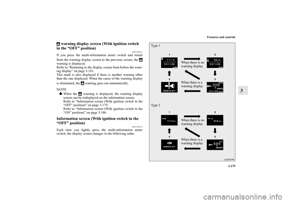
If you press the multi-information meter switch and return
from the warning display screen to the previous screen, the
warning is displayed.
Refer to “Returning to the display screen from before the warn-
ing display” on page 3-181.
This mark is also displayed if there is another warning other
than the one displayed. When the cause of the warning display
is eliminated, the warning goes out automatically.NOTE�When the warning is displayed, the warning display
screen can be redisplayed on the information screen.
Refer to “Information screen (With ignition switch in the
“OFF” position)” on page 3-179.
Refer to “Information screen (With ignition switch in the
“ON” position)” on page 3-186.Information screen (With ignition switch in the
“OFF” position)
N00555300154
Each time you lightly press the multi-information meter
switch, the display screen changes in the following order.
When there is no
warning display
When there is a
warning display Ty p e 1
When there is no
warning display
When there is a
warning display Ty p e 2
BK0151000US.book 179 ページ 2012年3月29日 木曜日 午後6時8分
Page 273 of 706
3-180 Features and controls
3
Odometer/Trip odometer
N00555400142
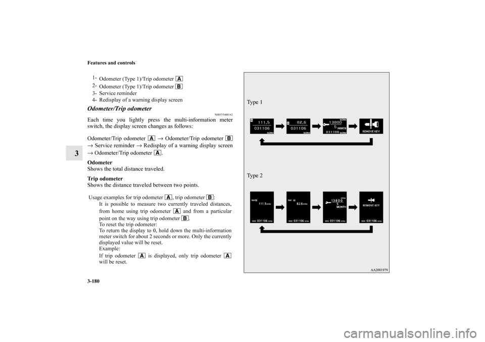
Each time you lightly press the multi-information meter
switch, the display screen changes as follows:
Odometer/Trip odometer → Odometer/Trip odometer
→ Service reminder → Redisplay of a warning display screen
→ Odometer/Trip odometer .
Odometer
Shows the total distance traveled.
Trip odometer
Shows the distance traveled between two points.1-
Odometer (Type 1)/Trip odometer
2-
Odometer (Type 1)/Trip odometer
3- Service reminder
4- Redisplay of a warning display screen
Usage examples for trip odometer , trip odometer :
It is possible to measure two currently traveled distances,
from home using trip odometer and from a particular
point on the way using trip odometer .
To reset the trip odometer:
To return the display to 0, hold down the multi-information
meter switch for about 2 seconds or more. Only the currently
displayed value will be reset.
Example:
If trip odometer is displayed, only trip odometer
will be reset.
Ty p e 2 Ty p e 1
BK0151000US.book 180 ページ 2012年3月29日 木曜日 午後6時8分
Page 275 of 706
3-182 Features and controls
3
Returning to the display screen from before the warn-
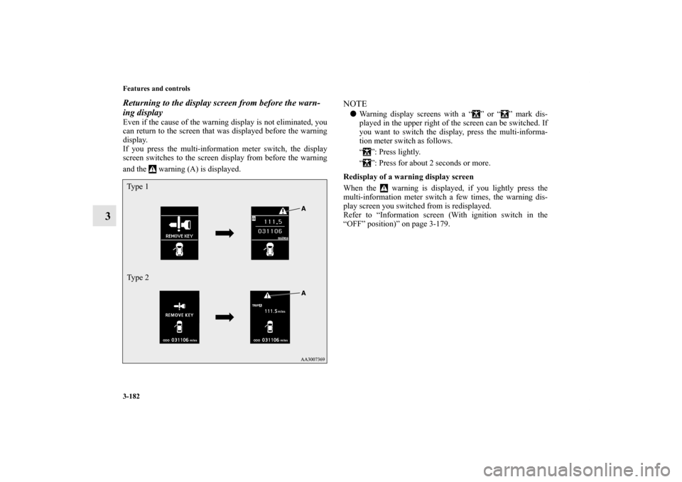
ing displayEven if the cause of the warning display is not eliminated, you
can return to the screen that was displayed before the warning
display.
If you press the multi-information meter switch, the display
screen switches to the screen display from before the warning
and the warning (A) is displayed.
NOTE�Warning display screens with a “ ” or “ ” mark dis-
played in the upper right of the screen can be switched. If
you want to switch the display, press the multi-informa-
tion meter switch as follows.
“ ”: Press lightly.
“ ”: Press for about 2 seconds or more.
Redisplay of a warning display screen
When the warning is displayed, if you lightly press the
multi-information meter switch a few times, the warning dis-
play screen you switched from is redisplayed.
Refer to “Information screen (With ignition switch in the
“OFF” position)” on page 3-179.
Ty p e 1
Ty p e 2BK0151000US.book 182 ページ 2012年3月29日 木曜日 午後6時8分