2013 MITSUBISHI iMiEV bonnet
[x] Cancel search: bonnetPage 206 of 258
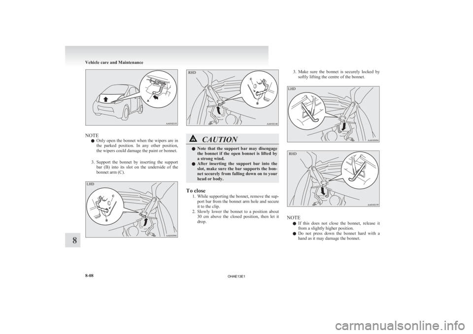
NOTE
l Only
open the bonnet when the wipers are in
the parked position. In any other position,
the wipers could damage the paint or bonnet.
3. Support the bonnet by inserting the support bar (B) into its slot on the underside of the
bonnet arm (C). CAUTION
l
Note
that the support bar may disengage
the bonnet if the open bonnet is lifted by
a strong wind.
l After inserting the support bar into the
slot, make sure the bar supports the bon-
net securely from falling down on to your
head or body.
To close 1. While
supporting the bonnet, remove the sup-
port bar from the bonnet arm hole and secure
it to the clip.
2. Slowly lower the bonnet to a position about 30 cm above the closed position, then let it
drop. 3. Make
sure the bonnet is securely locked by
softly lifting the centre of the bonnet. NOTE
l If
this does not close the bonnet, release it
from a slightly higher position.
l Do not press down the bonnet hard with a
hand as it may damage the bonnet. Vehicle care and Maintenance
8-08
8
OHAE13E1
Page 207 of 258
CAUTION
l
Be careful that hands or fingers are not
trapped when closing the bonnet.
l Before driving, make sure that the bon-
net is securely locked. An incompletely
locked bonnet can suddenly open while
driving. This can be extremely dangerous. Coolant/Hot water heater fluid
E08402100048
To check the coolant level
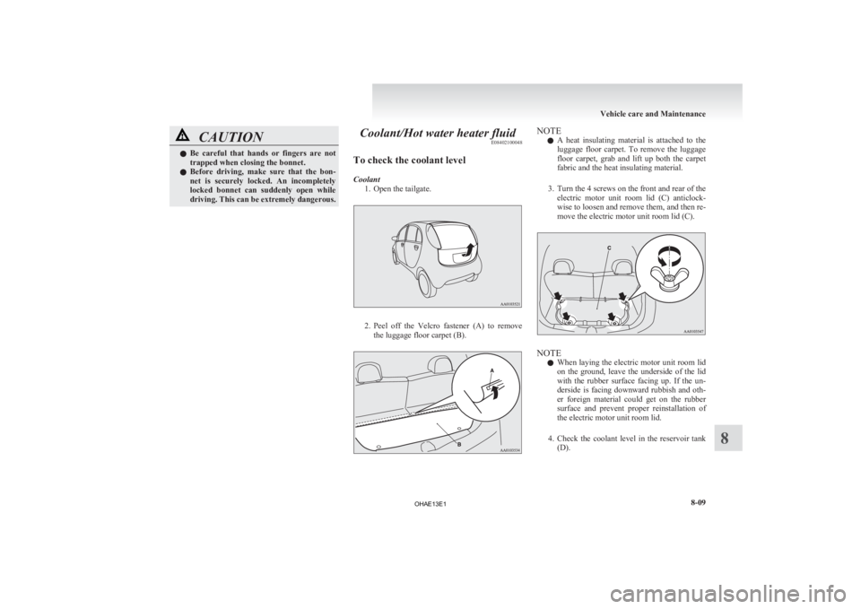
Coolant 1.
Open the tailgate. 2. Peel
off the Velcro fastener (A) to remove
the luggage floor carpet (B). NOTE
l A
heat insulating material is attached to the
luggage floor carpet. To remove the luggage
floor carpet, grab and lift up both the carpet
fabric and the heat insulating material.
3. Turn the 4 screws on the front and rear of the electric motor unit room lid (C) anticlock-
wise to loosen and remove them, and then re-
move the electric motor unit room lid (C). NOTE
l When
laying the electric motor unit room lid
on the ground, leave the underside of the lid
with the rubber surface facing up. If the un-
derside is facing downward rubbish and oth-
er foreign material could get on the rubber
surface and prevent proper reinstallation of
the electric motor unit room lid.
4. Check the coolant level in the reservoir tank (D). Vehicle care and Maintenance
8-09 8
OHAE13E1
Page 210 of 258
The brake fluid in the master cylinder should be
checked
when doing other work under the bonnet.
The brake system should also be checked for leak-
age at the same time.
If the brake fluid level falls markedly in a short
length of time, it indicates leaks from the brake sys-
tem.
If this occurs, we recommend you to have the vehi-
cle checked.
Fluid type
Use brake fluid conforming to DOT3 or DOT4
from a sealed container. The brake fluid is hygro-
scopic. Too much moisture in the brake fluid will
adversely affect the brake system, reducing the per-
formance. CAUTION
l
Take
care in handling brake fluid as it is
harmful to the eyes, may irritate your
skin and also damage painted surfaces.
l Use only the specified brake fluid.
Do not mix or add different brands of
brake fluid to prevent chemical reactions.
Do not let any petroleum-based fluid
touch, mix with, or get into the brake fluid.
This will damage the seals.
l Keep the reservoir tank cap closed to pre-
vent the brake fluid from deteriorating ex-
cept maintenance.
l Clean the filler cap before removing and
close the cap securely after maintenance. Auxiliary battery
E08402300011
The
condition of the auxiliary battery is very impor-
tant to keep the vehicle’s electrical system working
properly. Regular inspection and care are especial-
ly important in cold weather.
Removing and installing the auxiliary
battery upper cover E08402400012
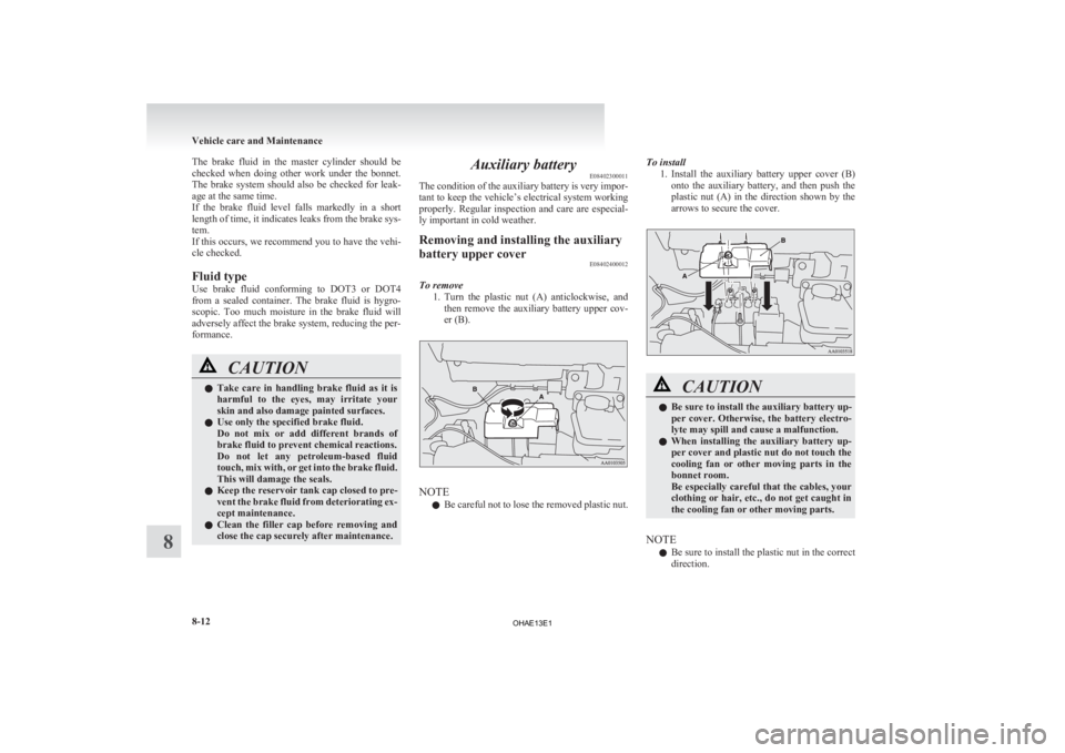
To remove 1. Turn
the plastic nut (A) anticlockwise, and
then remove the auxiliary battery upper cov-
er (B). NOTE
l Be
careful not to lose the removed plastic nut. To install
1. Install
the auxiliary battery upper cover (B)
onto the auxiliary battery, and then push the
plastic nut (A) in the direction shown by the
arrows to secure the cover. CAUTION
l
Be sure to install the auxiliary battery up-
per
cover. Otherwise, the battery electro-
lyte may spill and cause a malfunction.
l When installing the auxiliary battery up-
per cover and plastic nut do not touch the
cooling fan or other moving parts in the
bonnet room.
Be especially careful that the cables, your
clothing or hair, etc., do not get caught in
the cooling fan or other moving parts.
NOTE l Be
sure to install the plastic nut in the correct
direction. Vehicle care and Maintenance
8-12
8
OHAE13E1
Page 218 of 258

For cold and snowy weather
E08403700012
Ventilation slots
The
ventilation slots in front of the windscreen
should be kept clear of leaves or brushed clear after
heavy snowfall, so that the operation of the heating
and ventilation systems will not be impaired.
Weatherstripping
To prevent freezing of the weatherstripping on the
doors, bonnet, etc., they should be treated with sili-
cone grease.
Additional equipment
It is a good idea to carry a shovel or a short-han-
dled spade in the vehicle during the winter so that
you can clear away snow if you get stranded. A
small hand-brush for sweeping snow off the vehi-
cle and a plastic scraper for the windscreen and
rear window are also useful. Fusible links
E08403800013
The
fusible links will melt to prevent a fire if a
large current attempts to flow through certain elec-
trical systems.
In case of a melted fusible link, we recommend
you to have your vehicle inspected.
For the fusible links, please refer to “Passenger com-
partment fuse location table” on page 8-21 and
“Bonnet room fuse location table” on page 8-22. WARNING
l Fusible
links must not be replaced by any
other device. Failing to fit the correct fusi-
ble link may result in fire in the vehicle,
property destruction and serious or fatal
injuries at any time. Fuses
E08403900014
Fuse block location E08404000012
To prevent damage to the electrical system due to
shortcircuiting
or overloading, each individual cir-
cuit is provided with a fuse.
There are fuse blocks in the passenger compart-
ment and in the bonnet room.
NOTE
l Spare fuses are not provided. Please pur-
chase it from a MITSUBISHI MOTORS Au-
thorized Service Point or other locations.
Passenger compartment
The fuse block in the passenger compartment is lo-
cated in front of the driver’s seat at the position
shown in the illustration.
Press the tab (A) and remove the fuse cover (B). Vehicle care and Maintenance
8-20
8
OHAE13E1
Page 219 of 258

Bonnet room
In
the bonnet room, the fuse block is located as
shown in the illustration. Press the tab (A) and re-
move the cover. Fuse load capacity
E08404100013
The fuse capacity and the names of electrical sys-
tems
protected by the fuses are indicated on the
fuse block cover. Passenger compartment fuse location table
E08404200014 No. Sym-
bol Electrical system Capaci-
ties
1 Tail lamp (left)
7.5 A
2 Cigarette lighter/Ac-
cessory socket
15 A
3 — ——
4 Starter
7.5 A
5 Audio system amp
20 A
6 — ——
7 Tail lamp (right)
7.5 A
8 Outside rear-view mir-
rors
7.5 A
9 Control unit (Electric
motor unit)
7.5 A
* : Fusible link No. Sym-
bol Electrical system Capaci-
ties
10 Control unit
7.5 A
11 Rear fog lamp
10 A
12 Central door lock
15 A
13 Room lamp
10 A
14 Rear window wiper
15 A
15 Gauge
7.5 A
16 Relay
7.5 A
17 Heated seat
20 A
18 Option
10 A
19 Heated door mirror
7.5 A
20 Windscreen wiper
20 A
21 Reversing lamps
7.5 A
22 Demister
30 A
23 Heater
30 A
24 Auxiliary battery
30 A*
25 Radio
10 A
26 Electronic controlled
unit
15 A
* : Fusible link l
Some
fuses may not be installed on your ve-
hicle, depending on the vehicle model or spec-
ifications. Vehicle care and Maintenance
8-21 8
OHAE13E1
Page 220 of 258

l
The table above shows the main equipment
corresponding to each fuse.
Bonnet room fuse location table E08404300015No. Sym-
bol Electrical system Capaci-
ty
1 — ——
2 Auxiliary battery
30 A*
3 Electric motor switch
40 A*
4 Radiator fan motor
40 A*
5 Electric window con-
trol 40 A
*
6 Brake electric vacuum
pump 30 A
*
7 Electric motor unit con-
trol 15 A
8 Stop lamps 15 A
* : Fusible link No. Sym-
bol Electrical system Capaci-
ty
9 Front fog lamps 15 A
10 Water pump (Electric
motor unit) 15 A
11 Charge 10 A
12 Hazard warning flasher 10 A
13 Horn 10 A
14 Daytime running lamps 10 A
15 Traction battery cool-
ing fan motor 15 A
16 Water pump (Air con-
ditioning) 10 A
17 Headlamp low beam
(right) 20 A
18 Headlamp low beam
(left) 20 A
19 Headlamp high-beam
(right) 10 A
20 Headlamp high-beam
(left) 10 A
* : Fusible link l
Some
fuses may not be installed on your ve-
hicle, depending on the vehicle model or spec-
ifications.
l The table above shows the main equipment
corresponding to each fuse. Identification of fuse
E08404400016 Capacity Colour
7.5 A Brown
10 A Red
15 A Blue
20 A Yellow
30 A Green (fuse type) / Pink (fusible
link type)
40 A Green (fusible link type) Fuse replacement
E08404500017
1. Before
replacing a fuse, always turn off the
electrical circuit concerned and turn the elec-
tric motor switch to the “LOCK” position.
2. Remove the fuse puller (A) from the inside of the fuse cover in the passenger compart-
ment. 3. Referring
to the fuse load capacity table,
check the fuse pertaining to the problem. Vehicle care and Maintenance
8-22
8
OHAE13E1
Page 222 of 258

Outside
E08404800010Front1- Headlamps, low beam: 55 W (H11)
2-
Headlamps, high-beam: 60 W (HB3)
3- Front fog lamps*: 35 W (H8) Daytime running lamps*: 13 W (P13W)
4- Front turn-signal lamps: 21 W (W21W)
5- Position lamps: 5 W (W5W)
6- Side turn-signal lamps: 5 W (WY5W) *: if so equipped
Codes in parentheses indicate bulb types.
Rear 7- High-mounted stop lamp: 5 W (W5W)
8-
Stop and tail lamps
9- Rear turn-signal lamps: 21 W (WY21W)
10- Licence plate lamps: 5 W (W5W)
11- Rear fog lamp: 21 W (W21W)
12- Reversing lamps: 21 W (W21W) Codes in parentheses indicate bulb types.
NOTE l The stop and tail lamps use LEDs rather than
bulbs.
For repair and replacement, we recommend
you to contact a MITSUBISHI MOTORS Au-
thorized Service Point.
Inside E08404900011 1- Room lamp (rear): 8 W
2-
Room lamp (front) & map lamps: 8 W Removing and installing the headlamp
unit
E08405000022
Bulbs
for headlamps, position lamps or front turn-
signal lamps are replaced by removing the entire
headlamp unit from the vehicle.
Back side of the headlamp A- Headlamp (low beam)
B-
Headlamp (high-beam)
C- Position lamp
D- Front turn-signal lamp
Refer to the following section for replacement.
Headlamps (low beam) ® p. 8-28
Headlamps (high-beam) ® p. 8-29
Position lamps ® p. 8-30
Front turn-signal lamps ® p. 8-30
Use the following steps to remove the headlamp unit.
To remove
1. Open the bonnet. Refer to “Bonnet” on page8-07.
2. Press the tab (A) to remove the connector (B). Vehicle care and Maintenance
8-24
8
OHAE13E1
Page 242 of 258

Refill capacities
E01101304111Bonnet room
Electric motor unit room (under the floor of the luggage area) LHD
RHDSpecifications
9-08
9
OHAE13E1