2013 MITSUBISHI iMiEV ESP
[x] Cancel search: ESPPage 205 of 258

WARNING
l If it is necessary to do work in the bonnet
room with the electric motor running, be
especially careful that your clothing, hair,
etc., does not become caught by the fan,
or other moving parts.
l The fan can turn on automatically even if
the electric motor is not running. Turn
the electric motor switch to the “LOCK”
position to be safe while you work in the
bonnet room.
l Do not smoke, cause sparks or allow open
flames around the auxiliary battery.
l Be extremely cautious when working
around the auxiliary battery. It contains
poisonous and corrosive sulphuric acid.
l Improper handling of components and
materials used in the vehicle can endan-
ger your personal safety. We recommend
you to consult a specialist for necessary in-
formation. CAUTION
l
The
components inside the electric motor
unit room might be very hot to touch.
To avoid being burnt, make sure all com-
ponents have sufficiently cooled before be-
ginning an inspection.
These components are affixed with the la-
bel indicating precautions for handling.
Follow the instructions on the label. CAUTION
l
When
replacing the auxiliary battery, re-
move the connected positive (+) and nega-
tive (-) terminals after turning the electric
motor switch to the “LOCK” position
and waiting at least 2 minutes. If the aux-
iliary battery terminal is removed just af-
ter the electric motor switch is turned to
the “LOCK” position, this may cause dam-
age to components of the electric motor
unit. If the electric motor unit warning
lamp illuminates, do not replace the auxil-
iary battery. Contact a MITSUBISHI
MOTORS Authorized Service Point. Bonnet
E08402000018
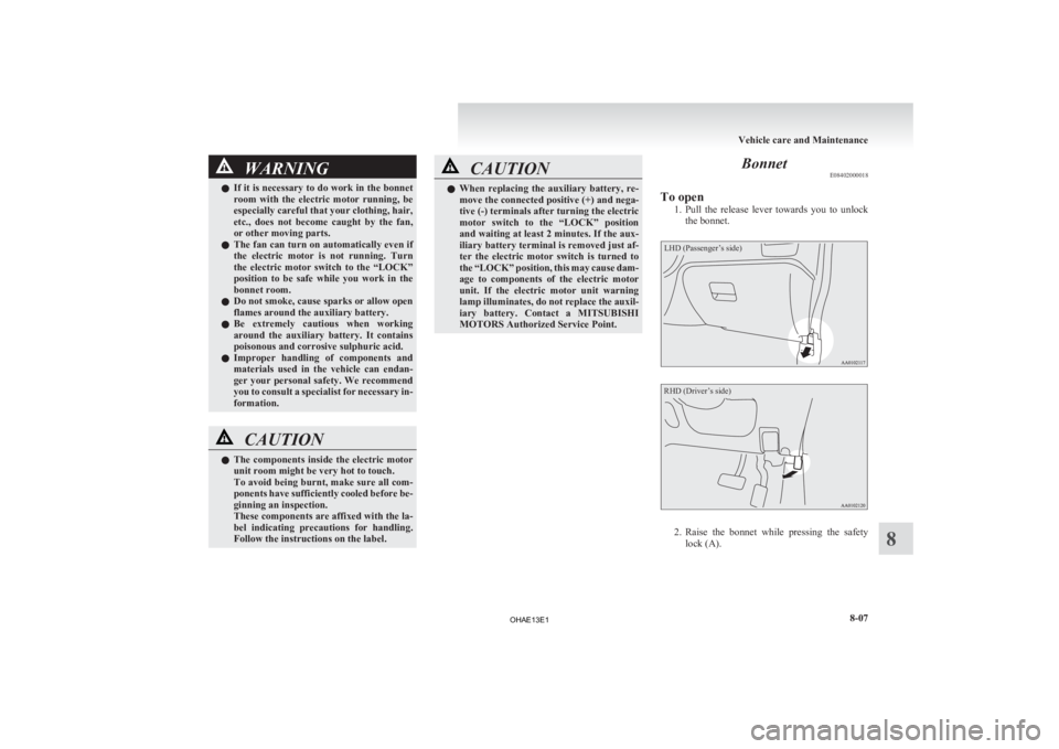
To open 1. Pull
the release lever towards you to unlock
the bonnet.
LHD (Passenger’s side)
RHD (Driver’s side) 2. Raise
the bonnet while pressing the safety
lock (A). Vehicle care and Maintenance
8-07 8
OHAE13E1
Page 210 of 258

The brake fluid in the master cylinder should be
checked
when doing other work under the bonnet.
The brake system should also be checked for leak-
age at the same time.
If the brake fluid level falls markedly in a short
length of time, it indicates leaks from the brake sys-
tem.
If this occurs, we recommend you to have the vehi-
cle checked.
Fluid type
Use brake fluid conforming to DOT3 or DOT4
from a sealed container. The brake fluid is hygro-
scopic. Too much moisture in the brake fluid will
adversely affect the brake system, reducing the per-
formance. CAUTION
l
Take
care in handling brake fluid as it is
harmful to the eyes, may irritate your
skin and also damage painted surfaces.
l Use only the specified brake fluid.
Do not mix or add different brands of
brake fluid to prevent chemical reactions.
Do not let any petroleum-based fluid
touch, mix with, or get into the brake fluid.
This will damage the seals.
l Keep the reservoir tank cap closed to pre-
vent the brake fluid from deteriorating ex-
cept maintenance.
l Clean the filler cap before removing and
close the cap securely after maintenance. Auxiliary battery
E08402300011
The
condition of the auxiliary battery is very impor-
tant to keep the vehicle’s electrical system working
properly. Regular inspection and care are especial-
ly important in cold weather.
Removing and installing the auxiliary
battery upper cover E08402400012
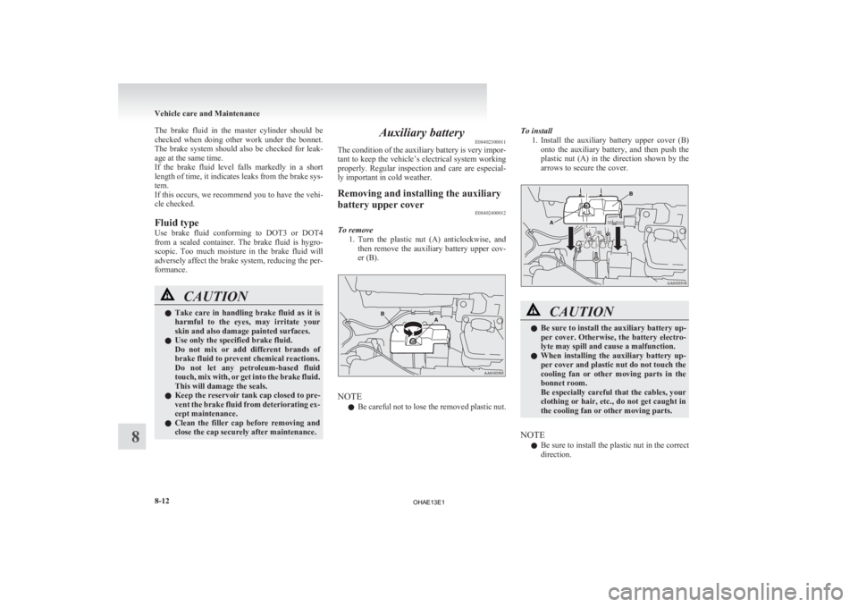
To remove 1. Turn
the plastic nut (A) anticlockwise, and
then remove the auxiliary battery upper cov-
er (B). NOTE
l Be
careful not to lose the removed plastic nut. To install
1. Install
the auxiliary battery upper cover (B)
onto the auxiliary battery, and then push the
plastic nut (A) in the direction shown by the
arrows to secure the cover. CAUTION
l
Be sure to install the auxiliary battery up-
per
cover. Otherwise, the battery electro-
lyte may spill and cause a malfunction.
l When installing the auxiliary battery up-
per cover and plastic nut do not touch the
cooling fan or other moving parts in the
bonnet room.
Be especially careful that the cables, your
clothing or hair, etc., do not get caught in
the cooling fan or other moving parts.
NOTE l Be
sure to install the plastic nut in the correct
direction. Vehicle care and Maintenance
8-12
8
OHAE13E1
Page 220 of 258

l
The table above shows the main equipment
corresponding to each fuse.
Bonnet room fuse location table E08404300015No. Sym-
bol Electrical system Capaci-
ty
1 — ——
2 Auxiliary battery
30 A*
3 Electric motor switch
40 A*
4 Radiator fan motor
40 A*
5 Electric window con-
trol 40 A
*
6 Brake electric vacuum
pump 30 A
*
7 Electric motor unit con-
trol 15 A
8 Stop lamps 15 A
* : Fusible link No. Sym-
bol Electrical system Capaci-
ty
9 Front fog lamps 15 A
10 Water pump (Electric
motor unit) 15 A
11 Charge 10 A
12 Hazard warning flasher 10 A
13 Horn 10 A
14 Daytime running lamps 10 A
15 Traction battery cool-
ing fan motor 15 A
16 Water pump (Air con-
ditioning) 10 A
17 Headlamp low beam
(right) 20 A
18 Headlamp low beam
(left) 20 A
19 Headlamp high-beam
(right) 10 A
20 Headlamp high-beam
(left) 10 A
* : Fusible link l
Some
fuses may not be installed on your ve-
hicle, depending on the vehicle model or spec-
ifications.
l The table above shows the main equipment
corresponding to each fuse. Identification of fuse
E08404400016 Capacity Colour
7.5 A Brown
10 A Red
15 A Blue
20 A Yellow
30 A Green (fuse type) / Pink (fusible
link type)
40 A Green (fusible link type) Fuse replacement
E08404500017
1. Before
replacing a fuse, always turn off the
electrical circuit concerned and turn the elec-
tric motor switch to the “LOCK” position.
2. Remove the fuse puller (A) from the inside of the fuse cover in the passenger compart-
ment. 3. Referring
to the fuse load capacity table,
check the fuse pertaining to the problem. Vehicle care and Maintenance
8-22
8
OHAE13E1
Page 221 of 258

B- Fuse is OK
C- Blown fuse
NOTE l If
any system does not function but the fuse
corresponding to that system is normal, there
may be a fault in the system elsewhere. We
recommend you to have your vehicle checked.
4. Insert a new fuse of the same capacity by us- ing the fuse puller into the same place at the
fuse block. CAUTION
l
If
the newly inserted fuse blows again af-
ter a short time, we recommend you to
have the electrical system checked to find
the cause and rectify it.
l Never use a fuse with a capacity larger
than that specified or any substitute, such
as wire, foil, etc.; doing so will cause the
circuit wiring to heat up and this could
cause fire. Replacement of lamp bulbs
E08404600018
Before
replacing a bulb, ensure the lamp is off. Do
not touch the glass part of the new bulb with your
bare fingers; the skin oil left on the glass will evap-
orate when the bulb gets hot and the vapour will
condense on the reflector and dim the surface. CAUTION
l
Bulbs
are extremely hot immediately af-
ter being turned off.
When replacing a bulb, wait for it to cool
sufficiently before touching it. You could
otherwise be burnt.
NOTE l If
you are unsure of how to carry out the
work as required, we recommend you to con-
sult a specialist.
l Be careful not to scratch the vehicle body
when removing a lamp or lens.
l When it rains or when the vehicle has been
washed, the inside of the lens sometimes be-
comes foggy. This is the same phenomenon
as when window glass mists up on a humid
day, and does not indicate a functional prob-
lem.
When the lamp is switched on, the heat will
remove the fog. However, if water gathers in-
side the lamp, we recommend you to have
the lamp checked.
Bulb capacity E08404700019
When replacing a bulb, use a new bulb with the
same wattage and colour. Vehicle care and Maintenance
8-23 8
OHAE13E1
Page 236 of 258

Vehicle labeling
E01100102899
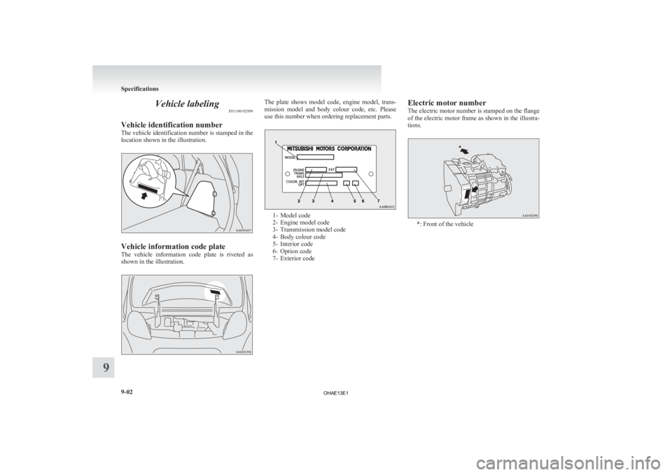
Vehicle identification number
The
vehicle identification number is stamped in the
location shown in the illustration. Vehicle information code plate
The
vehicle information code plate is riveted as
shown in the illustration. The plate shows model code, engine model, trans-
mission
model and body colour code, etc. Please
use this number when ordering replacement parts. 1- Model code
2-
Engine model code
3- Transmission model code
4- Body colour code
5- Interior code
6- Option code
7- Exterior code Electric motor number
The electric motor number is stamped on the flange
of
the electric motor frame as shown in the illustra-
tions. *: Front of the vehicleSpecifications
9-02
9
OHAE13E1