Page 172 of 258

l
The unit may not successfully play back a
CD-R/RW that was made by the combina-
tion of writing software, a CD recorder
(CD-R/RW drive) and a disc if they are in-
compatible with one another.
l This player cannot play the CD-R/RW discs
if the session is not closed.
l This player cannot play CD-R/RW discs
which contain other than CD-DA or MP3 da-
ta (Video CD, etc.).
l Be sure to observe the handling instructions
for the CD-R/RW disc. WARNING
l Operating
the CD player in a manner oth-
er than specifically instructed herein may
result in hazardous radiation exposure.
Do not remove the cover and attempt to
repair the CD player by yourself. There
are no user serviceable parts inside. In
case of malfunction, we recommend you
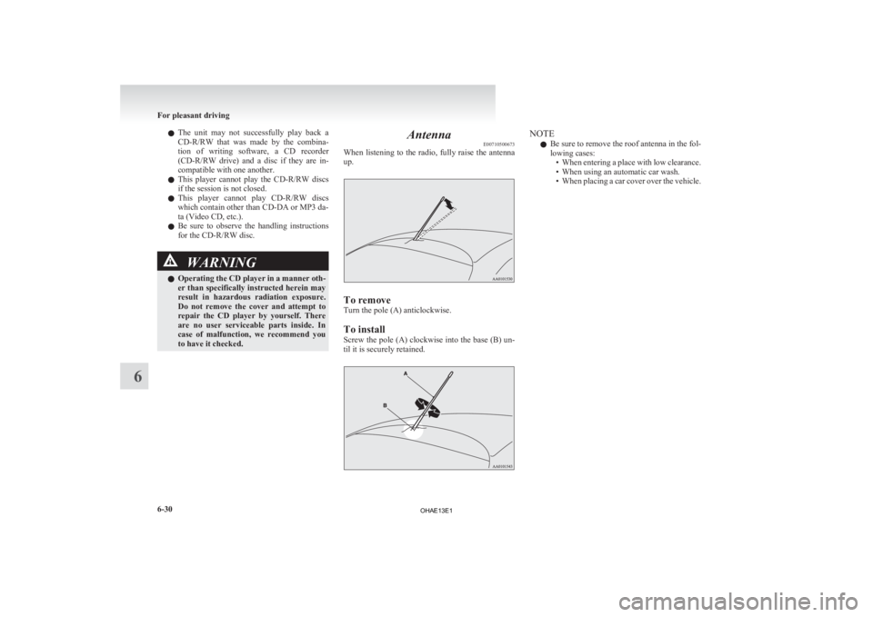
to have it checked. Antenna
E00710500673
When
listening to the radio, fully raise the antenna
up. To remove
Turn the pole (A) anticlockwise.
To install
Screw
the pole (A) clockwise into the base (B) un-
til it is securely retained. NOTE
l Be
sure to remove the roof antenna in the fol-
lowing cases: • When entering a place with low clearance.
• When using an automatic car wash.
• When placing a car cover over the vehicle. For pleasant driving
6-30
6
OHAE13E1
Page 192 of 258

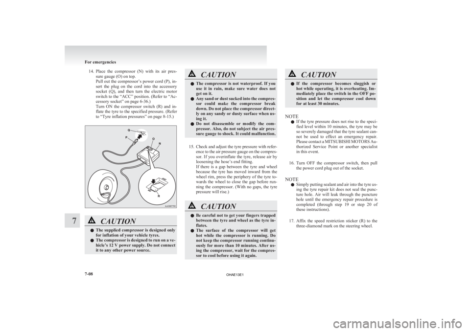
14. Place the compressor (N) with its air pres-
sure gauge (O) on top.
Pull out the compressor’s power cord (P), in-
sert the plug on the cord into the accessory
socket (Q), and then turn the electric motor
switch to the “ACC” position. (Refer to “Ac-
cessory socket” on page 6-36.)
Turn ON the compressor switch (R) and in-
flate the tyre to the specified pressure. (Refer
to “Tyre inflation pressures” on page 8-15.) CAUTION
l
The
supplied compressor is designed only
for inflation of your vehicle tyres.
l The compressor is designed to run on a ve-
hicle’s 12 V power supply. Do not connect
it to any other power source. CAUTION
l
The
compressor is not waterproof. If you
use it in rain, make sure water does not
get on it.
l Any sand or dust sucked into the compres-
sor could make the compressor break
down. Do not place the compressor direct-
ly on any sandy or dusty surface when us-
ing it.
l Do not disassemble or modify the com-
pressor. Also, do not subject the air pres-
sure gauge to shock. It could malfunction.
15. Check
and adjust the tyre pressure with refer- ence to the air pressure gauge on the compres-
sor. If you overinflate the tyre, release air by
loosening the hose’s end fitting.
If there is a gap between the tyre and wheel
because the tyre has moved inward from the
wheel rim, press the periphery of the tyre to-
wards the wheel to close the gap before run-
ning the compressor. (With no gaps, the tyre
pressure will rise.) CAUTION
l
Be
careful not to get your fingers trapped
between the tyre and wheel as the tyre in-
flates.
l The surface of the compressor will get
hot while the compressor is running. Do
not keep the compressor running continu-
ously for more than 10 minutes. After us-
ing the compressor, wait for the compres-
sor to cool before using it again. CAUTION
l
If
the compressor becomes sluggish or
hot while operating, it is overheating. Im-
mediately place the switch in the OFF po-
sition and let the compressor cool down
for at least 30 minutes.
NOTE l If
the tyre pressure does not rise to the speci-
fied level within 10 minutes, the tyre may be
so severely damaged that the tyre sealant can-
not be used to effect an emergency repair.
Please contact a MITSUBISHI MOTORS Au-
thorized Service Point or another specialist
in this event.
16. Turn OFF the compressor switch, then pull the power cord plug out of the socket.
NOTE l Simply putting sealant and air into the tyre us-
ing the tyre repair kit does not seal the punc-
ture hole. Air will leak through the puncture
hole until the emergency repair procedure is
completed (through step 19 or step 20 of
these instructions).
17. Affix the speed restriction sticker (R) to the three-diamond mark on the steering wheel. For emergencies
7-08
7
OHAE13E1
Page 247 of 258

P
Parking 5-04
Parking brake 5-03
Position lamps Bulb capacity
8-24
Indication lamp 4-09
Replacement 8-30
Power down warning lamp 4-11
Precautions to observe when using wipers and wash-
ers 4-18
Pregnant women restraint 3-10
Puncture Tyre repair kit 7-04
QQuick charging 1-12
RRadio
LW/MW/FM electronic tuning radio with CD
player 6-10
Ready indicator
4-09
Rear combination lamps Bulb capacity 8-24
Replacement 8-33
Rear fog lamp Bulb capacity 8-24
Indication lamp 4-09
Replacement 8-32
Switch 4-16
Rear room lamp Bulb capacity 8-24
Rear seat 3-05
Rear turn-signal lamps Bulb capacity 8-24 Replacement 8-30,8-33
Rear window demister switch 4-18
Rear-view mirror Inside 5-05
Outside 5-05
Refill capacities
9-08
Regenerative braking 02
Regular charging 1-08
Replacement of lamp bulbs 8-23
Reversing lamps Bulb capacity 8-24
Replacement 8-33
Roof carrier precaution 5-20
Room lamp (front) 6-37
Room lamp (rear) 6-38
S Safe driving techniques 5-03
Seat belt 3-08
Child restraint 3-11
Force limiter
3-11
Inspection 3-20
Pregnant women restraint 3-10
Pretensioner 3-11
Seat belt reminder/warning lamp (for driver and
front passenger) 3-09
Warning lamp (for rear passenger) 3-10
Seats Adjustment 3-03
Front seat 3-03
Head restraints 3-07
Heated seats 3-04
Rear seat 3-05
Secret box 6-39
Selector lever 5-09
Service precaution 8-06
Service reminder 4-03,4-04
Side turn-signal lamps Bulb capacity 8-24
Replacement
8-30,8-33
Snow tyres 8-16
Specifications 9-02
Speedometer 4-02
Starting the electric motor unit 5-08
Steering wheel lock 5-08
Stop lamps Bulb capacity 8-24
Replacement 8-33
Storage spaces 6-39 Glove box 6-39
Secret box 6-39
Sun visors 6-35
Supplemental restraint system 3-20 Servicing 3-30
Warning lamp 3-29
T Tail lamps
Bulb capacity
8-24
Replacement 8-33
Tailgate 2-08
Towing 7-10
Traction battery 02
Transmission 5-09 Driving the vehicle 5-11
Selector lever 5-09
Selector lever position indicator 5-10
Tripmeter 4-03,4-04
Turn-signal indication lamps 4-09
Turn-signal lever 4-14
Tyre repair kit 7-04
Tyres 8-14 Inflation pressures 8-15
Size (tyre and wheel) 9-06
Snow tyres 8-16
Tread wear indicators 8-16 Alphabetical index
3
OHAE13E1