2013 MITSUBISHI iMiEV parking brake
[x] Cancel search: parking brakePage 124 of 258

NOTE
l Apply
sufficient force to the parking brake
lever to hold the vehicle stationary after the
foot brake is released.
l If the parking brake does not hold the vehicle
stationary after the foot brake is released,
have your vehicle checked immediately.
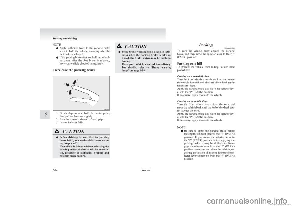
To release the parking brake 1- Firmly
depress and hold the brake pedal,
then pull the lever up slightly.
2- Push the button at the end of hand grip.
3- Lower the lever fully. CAUTION
l
Before
driving, be sure that the parking
brake is fully released and the brake warn-
ing lamp is off.
If a vehicle is driven without releasing the
parking brake, the brake will be overhea-
ted, resulting in ineffective braking and
possible brake failure. CAUTION
l
If
the brake warning lamp does not extin-
guish when the parking brake is fully re-
leased, the brake system may be malfunc-
tioning.
Have your vehicle checked immediately.
For details, refer to “Brake warning
lamp” on page 4-09. Parking
E00600601534
To
park the vehicle, fully engage the parking
brake, and then move the selector lever to the “P”
(PARK) position.
Parking on a hill
To prevent the vehicle from rolling, follow these
procedures:
Parking on a downhill slope
Turn the front wheels towards the kerb and move
the vehicle forward until the kerb side wheel gently
touches the kerb.
Apply the parking brake and place the selector lev-
er into the “P” (PARK) position.
If necessary, apply chocks to the wheels.
Parking on an uphill slope
Turn the front wheels away from the kerb and
move the vehicle back until the kerb side wheel gen-
tly touches the kerb.
Apply the parking brake and place the selector lev-
er into the “P” (PARK) position.
If necessary, apply chocks to the wheels.
NOTE
l Be sure to apply the parking brake before
moving the selector lever to the “P” (PARK)
position. If you move the selector lever to
the “P” (PARK) position before applying the
parking brake, it may be difficult to disen-
gage the selector lever from the “P” (PARK)
position when you next drive the vehicle, re-
quiring application of a strong force to the se-
lector lever to move it from the “P” (PARK)
position. Starting and driving
5-04
5
OHAE13E1
Page 128 of 258

CAUTION
l
If the ready indicator goes out while driv-
ing, the brake servomechanism will cease
to function and braking efficiency will de-
teriorate. Also, the power steering system
may not operate, the steering wheel feels
heavy when turning it.
l When the ready indicator has turned off,
turn the electric motor switch to the
“LOCK” position.
Leaving the electric motor switch in the
“ON” or “ACC” position and using elec-
trical devices such as the audio system for
a long time could cause the auxiliary bat-
tery to go flat and prevent the electric mo-
tor unit from being started. Steering wheel lock
E00601500692
To lock
Remove the key at the “LOCK” position.
Turn the steering wheel until it is locked.
To unlock
Turn
the key to the “ACC” position while moving
the steering wheel slightly right and left. CAUTION
l
Remove the key when leaving the vehicle.
In some countries, it is prohibited to leave
the key in the vehicle when parked. Starting the electric motor unit
E00629300012 CAUTION
l
Never
attempt to start the electric motor
unit by pushing or pulling the vehicle.
The starting procedure is as follows: 1. Insert
the key in the electric motor switch
and fasten the seat belt.
2. Make sure the parking brake is applied.
3. Depress and hold the brake pedal.
4. Make sure the selector lever is in the “P” (PARK) position. NOTE
l The
electric motor unit will not start unless
the selector lever is in the “P” (PARK) posi-
tion. Starting and driving
5-08
5
OHAE13E1
Page 131 of 258

WARNING
l Avoid sudden regenerative braking when
driving on wet or icy roads. Using sudden
regenerative braking under these condi-
tions could cause the vehicle to skid, re-
sulting in a serious accident.
NOTE l When
the traction battery level is nearly full
or the traction battery temperature is low, the
regenerative braking performance may be
weakened. In this case, drive the vehicle at a
low speed.
“C” COMFORT
This position gives weaker regenerative braking
than the “D” (DRIVE) position. It enables relaxed
driving in circumstances in which you do not accel-
erate or decelerate much (for example, suburban
driving). It is intended for long cruising. Driving the vehicle
E00629700016
Operation of the transmission E00629800020 CAUTION
l
Before
selecting a position with the elec-
tric motor unit running and the vehicle
stationary, fully depress the brake pedal
to prevent the vehicle from creeping.
The vehicle will begin to move as soon as
the transmission is engaged, the brakes
should only be released when you are
ready to drive away.
l Depress the brake pedal with the right
foot at all times.
Using the left foot could cause driver move-
ment delay in case of an emergency.
l Operating the accelerator pedal while the
other foot is resting on the brake pedal
will affect braking efficiency and may
cause premature wear of brake pads.
Waiting E00630900018
For short waiting periods, such as at traffic signals
the
vehicle can be left in selector lever position and
held stationary with the service brake.
For longer waiting periods with the electric motor
unit running, place the selector lever in the “N”
(NEUTRAL) position and apply the parking brake,
while holding the vehicle stationary with the serv-
ice brake. CAUTION
l
Never
hold the vehicle stationary while in
transmission on a hill with the accelera-
tor, always apply the parking brake and/
or service brake.
Parking E00631000016
To park the vehicle, first bring it to a complete
stop,
fully engage the parking brake, and then
move the selector lever to the “P” (PARK) position.
If you are going to leave the vehicle unattended, al-
ways switch off the electric motor unit and carry
the key.
NOTE
l On a slope, be sure to apply the parking
brake before moving the selector lever to the
“P” (PARK) position. If you move the selec-
tor lever to the “P” (PARK) position before
applying the parking brake, it may be diffi-
cult to disengage the selector lever from the
“P” (PARK) position when you next drive
the vehicle, requiring application of a strong
force to the selector lever to move it from the
“P” (PARK) position. Starting and driving
5-11 5
OHAE13E1
Page 182 of 258

Cup holder
E00714500974CAUTION
l
Do not drink beverages while driving.
This is distracting and could cause an ac-
cident.
l Beverages can be spilled owing to vibra-
tion or other movement during vehicle op-
eration. Be careful not to get scalded by a
hot beverage if it is spilled.
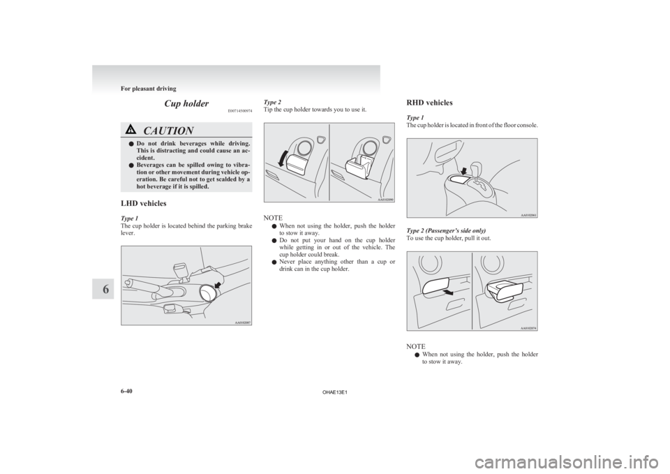
LHD vehicles
Type 1
The
cup holder is located behind the parking brake
lever. Type 2
Tip the cup holder towards you to use it.
NOTE
l When
not using the holder, push the holder
to stow it away.
l Do not put your hand on the cup holder
while getting in or out of the vehicle. The
cup holder could break.
l Never place anything other than a cup or
drink can in the cup holder. RHD vehicles
Type 1
The
cup holder is located in front of the floor console. Type 2 (Passenger’s side only)
To use the cup holder, pull it out.
NOTE
l When
not using the holder, push the holder
to stow it away. For pleasant driving
6-40
6
OHAE13E1
Page 186 of 258

If the vehicle breaks down
E00800101355
If
the vehicle breaks down on the road, move it to
the shoulder and use the hazard warning flashers and/
or the warning triangle etc.
Refer to “Hazard warning flasher switch” on page
4-15. WARNING
l If
you are not able to safely assess the ve-
hicle due to vehicle damage, do not touch
the vehicle. Leave the vehicle and contact
a MITSUBISHI MOTORS Authorized
Service Point or another specialist and
convey that this is an electric vehicle first.
If the ready indicator goes out while
driving
Vehicle
operation and control are affected if the
ready indicator goes out while driving. Before mov-
ing the vehicle to a safe area, be aware of the fol-
lowing:
l The brake booster may become inoperative
and the pedal effort will increase. Press
down the brake pedal harder than usual.
l The power steering system may not operate,
the steering wheel feels heavy when turning it. Emergency starting
E00800502819
If
the electric motor unit cannot be started because
the auxiliary battery is weak or dead, the battery
from another vehicle can be used with jumper ca-
bles to start the electric motor unit. WARNING
l To
start the electric motor unit by using
jumper cables from another vehicle, per-
form the correct procedures according to
the instruction below. Incorrect proce-
dures could result in a fire or explosion
or damage to the vehicles. CAUTION
l
The
electric motor unit cannot be started
by pulling or pushing the vehicle.
l Always wear protective eye goggles when
working near the battery.
l Keep the battery out of the reach of chil-
dren.
l Do not attempt jump start the auxiliary
battery while the traction battery is being
charged.
Doing so could damage the charging
equipment or the vehicle.
1. Get
the vehicles close enough so the jumper cables can reach, but be sure the vehicles
aren’t touching each other. CAUTION
l
Check
the other vehicle. It must have a 12-
volt battery.
If the other system isn’t 12-volt, shorting
can damage both vehicles.
2. Turn
off all lamps, heater and other electrical loads.
3. Set the parking brake firmly on your vehicle and move the selector lever into the “P” posi-
tion.
4. Set the parking brake firmly on another vehi- cle. Put an A/T in “P” (PARK) or a M/T in
“N” (Neutral).
5. Turn the ignition switch or the electric motor switch to the “LOCK” position. WARNING
l Perform
step 5 on both vehicles before-
hand.
Make sure that the cables or your clothes
cannot be caught by the fan or drive belt.
Personal injury could result.
6. Remove
the battery cover, and then make sure auxiliary battery electrolyte is at the prop-
er level.
Refer to “Auxiliary battery” on page 8-12. For emergencies
7-02
7
OHAE13E1
Page 190 of 258

l
Use the tyre sealant only at ambient tempera-
tures of -30 °C to + 60 °C.
l Effect an emergency repair without pulling
out the object (nail, screw, etc.) that is stuck
in the tyre.
l Do not use the tyre sealant if the tyre has
been damaged by being driven when insuffi-
ciently inflated (e.g. bumps, cuts, cracks etc.
on the tyre).
l Wipe tyre sealant off the paintwork immedi-
ately with a damp cloth.
l Immediately wash clothes contaminated with
tyre sealant.
Before repairing a tyre, first stop your vehicle in a
safe, flat location. 1. Park the vehicle on level and stable ground.
2. Set the parking brake firmly.
3. Move the selector lever to the “P” (PARK)position and turn the electric motor switch to
the “LOCK” position.
4. Turn on the hazard warning flashers and set up a warning triangle, flashing signal lamp,
etc., at an adequate distance from the vehi-
cle, and have all your passengers leave the ve-
hicle.
5. Take out the tyre repair kit.
6. Shake the tyre sealant bottle well. NOTE
l In
cold conditions (when the ambient temper-
ature is 0 °C or lower), thickening of the tyre
sealant can make the tyre sealant hard to
squeeze out of the bottle. Warm the bottle in-
side the vehicle.
7. Take the cap (C) off the tyre sealant bottle (D). Do not remove the seal (E). Screw the
filler hose (D) onto the bottle (E). As you
screw the filler hose onto the bottle, the seal
will break, allowing the sealant to be used. CAUTION
l
If
you shake the bottle after screwing on
the hose, sealant may spray out of the hose.
8. Take the valve cap (G) off the tyre valve (H), then
press the valve remover (I) onto the
valve as illustrated. Allow all of the air in the
tyre to escape. 9. Remove
the valve insert (J) by turning it anti-
clockwise using the valve remover (I). Put
the removed valve insert in a clean place so
it does not get dirty. For emergencies
7-06
7
OHAE13E1
Page 197 of 258

On a snow-covered or frozen road
l When
driving on a snow-covered or frozen
road, it is recommended that you use snow
tyres or tyre chains.
Refer to the “Snow tyres” and “Tyre chains”
sections.
l Avoid high-speed driving, sudden accelera-
tion, sudden braking, and sharp turns.
l Depressing the brake pedal during travel on
snowy or icy roads may cause tyre slippage
and skidding. Tyres may slip if the ability of
the tyres to grip the road surface lessens.
This may make it more difficult to stop the
vehicle with normal braking operations. For
vehicles with an anti-lock brake system
(ABS), firmly depress and hold down the
brake pedal.
l Allow extra distance between your vehicle
and the vehicle in front of you, and avoid sud-
den braking.
l Accumulation of ice on the braking system
can cause the wheels to lock. Pull away from
a standstill slowly after confirming safety
around the vehicle. CAUTION
l
Do
not press the accelerator pedal rapid-
ly. If the wheels break free of the ice, the
vehicle could suddenly start moving and
possibly cause an accident.
On a bumpy or rutted road
Drive
as slow as possible when driving on bumpy
or rutted roads. CAUTION
l
The
impact on tyres and/or wheels when
driving on a bumpy or rutted road can
damage the tyre and/or wheel.
l The vehicle’s body, bumper, muffler and
other parts may be damaged if the vehi-
cle is:
• driven over a step (for example, at theentrance or exit of a parking lot);
• parked too closely against a kerb or parking block, or by the side of a road
with kerbstones;
• driven on a steep slope; For emergencies
7-13 7
OHAE13E1
Page 245 of 258

A
Accessory (Installation) 04
Accessory socket 6-36
Active stability control (ASC)
5-18
Additional equipment 8-20
Air conditioning Important operation tips for the air condition-
ing 6-09
Air purifier 6-09
Airbag 3-20
Antenna 6-30
Anti-lock brake system (ABS) 5-15 Warning lamp 5-16
Assist grips 6-41
Audio Error codes 6-26
Handling of compact discs 6-29
LW/MW/FM electronic tuning radio with CD
player 6-10
Auxiliary battery 8-12 Specification 9-05
Auxiliary battery charge warning lamp 4-10
BBasic knowledge for charging 1-04
Battery
Auxiliary battery
8-12
Auxiliary battery charge warning lamp 4-10
Discharged battery (Emergency starting) 7-02
Disposal information for used batteries 05
Traction battery 02
Bonnet 8-07
Brake assist system 5-15
Brake Anti-lock brake 5-15
Braking 5-14 Fluid 8-11,9-08
Parking brake 5-03
Warning lamp 4-09
Bulb capacity
8-23C Capacities 9-08
Card holder 6-36,6-39
Cargo loads 5-20
Central door locks 2-06
Charging indicator
4-09
Charging Quick charging 1-12
Regular charging 1-08
Child restraint 3-11
Child-protection rear doors 2-07
Cleaning Exterior of your vehicle 8-03
Interior of your vehicle 8-02
Plastic, vinyl leather, etc. 8-02
Clock 6-31
Cold Cautions and actions to deal with intense
cold 08
Combination headlamps and dipper switch 4-11
Coolant 8-09,9-08
Cruising range 03,9-07
Cruising range indicator 4-03,4-06
Cup holder 6-40
D Daytime running lamps 4-13
Bulb capacity
8-24
Replacement 8-31
Demister (rear window) 4-18
Digital clock 6-31
Dimensions 9-03 Dipper (High/Low beam change) 4-13
Door ajar warning lamp 4-10
Doors
Central door locks 2-06
Child-protection
2-07
Lock and unlock 2-05
Driving the vehicle 5-11
Driving, alcohol and drugs 5-02
E Economical driving 5-02
Electric motor switch
5-07
Electric motor unit Warning lamp 4-10
Electric motor Number 9-02
Specifications 9-05
Electric power steering system (EPS) 5-17
Electric window control 2-09 Driver’s switches 2-09
Lock switch 2-09
Passenger’s switches 2-09
Timer function 2-10
Electronic immobilizer (Anti-theft starting sys-
tem) 2-02
Emergency starting 7-02
Energy level gauge 4-06
Energy usage indicator 4-03
Error codes 6-26
EV charging cable 1-05
Exterior and interior lamp operation 8-19
F Fluid capacities and lubricants 9-08
Fluid
Brake fluid 8-11,9-08
Coolant 8-09 Alphabetical index
1
OHAE13E1