2013 MITSUBISHI iMiEV change time
[x] Cancel search: change timePage 64 of 258

NOTE
l The
indication lamp (3) comes on each time
a switch is pressed.
l If the UNLOCK switch (2) is pressed and
any of the doors or the tailgate is not opened
within approximately 30 seconds, relocking
will automatically occur.
l It is possible to modify functions as follows:
For further information, please contact your
MITSUBISHI MOTORS Authorized Service
Point.
• The time for automatic relocking can bechanged.
• The confirmation function (flashing of the turn-signal lamps) can be set to oper-
ate only when the doors and the tailgate
are locked or only when the doors and
the tailgate are unlocked.
• The confirmation function (this indicates locking or unlocking of the doors and the
tailgate with the flash of the turn-signal
lamps) can be deactivated.
• The number of times the turn-signal lamps are flashed by the confirmation
function can be changed.
l The keyless entry system does not operate in
the following conditions:
• The key is left in the key cylinder.
• The door or the tailgate is open.
l The remote control switch will operate with-
in approximately 4 m from the vehicle. How-
ever, the operating range of the remote con-
trol switch may change if the vehicle is loca-
ted near a power station, or radio/TV broad-
casting station.
l If either of the following problems occurs,
the battery may be exhausted. • The remote control switch is operated at
the correct distance from the vehicle, but
the doors and the tailgate are not locked/
unlocked in response.
• The indication lamp (3) is dim or does not come on.
For further information, please contact
your MITSUBISHI MOTORS Author-
ized Service Point.
If you replace the battery yourself, refer
to “Procedure for replacing the remote
control switch battery” on page 2-04.
l If your remote control switch is lost or dam-
aged, please contact your MITSUBISHI
MOTORS Authorized Service Point for a re-
placement remote control switch.
l If you wish to add a remote control switch,
we recommend you to contact a
MITSUBISHI MOTORS Authorized Service
Point.
A maximum of 4 remote control switches are
available for your vehicle.
Operation of the outside rear-view mir-
rors E00310800119
To fold
Within
30 seconds of locking the doors and the tail-
gate using the LOCK switch (1), press the LOCK
switch twice rapidly to fold the outside rear-view
mirrors.
To extend
Within 30 seconds of unlocking the doors and the
tailgate using the UNLOCK switch (2), press the
UNLOCK switch twice rapidly to return the out-
side rear-view mirrors to their extended positions. Procedure for replacing the remote
control switch battery
E00309500204
1. Before
replacing the battery, remove static
electricity from your body by touching a met-
al part such as doorknob of the room.
2. Remove the screw (A) from the remote con- trol switch. 3. With
the MITSUBISHI mark facing you, in-
sert the clothcovered tip of a straight blade
(or minus) screwdriver into the notch in the
remote control switch case and use it to open
the case. Locking and unlocking
2-04
2
OHAE13E1
Page 102 of 258

Instruments
E005001012511- Energy level gauge
2-
Energy usage indicator
3- Odometer/Tripmeter/Meter illumination con- trol/Service reminder/Cruising range indica-
tor
4- Speedometer (km/h or MPH)
5- Reset button/Daytime dipper button/Selector button Speedometer
E00500201050
When
the electric motor switch is in the “ON” posi-
tion, the speedometer indicates the vehicle speed in
kilometers per hour (km/h) (Type 1) or miles per
hour (MPH) (Type 2).
Type 1 Type 2 NOTE
l The
display setting can be changed to the pre-
ferred units (km or miles) (Type 2).
Refer to “Changing the display unit*” on
page 4-02.
Changing the display unit* E00529500026
It is possible to select the speedometer’s display unit.
1. Press
the reset button (A) to display the od-
ometer (B).
(Refer to “To change the display” on page
4-03.) 2. Keep
the reset button pressed for two sec-
onds or longer to change the display unit
from MPH to km/h or from km/h to MPH. NOTE
l Once
the display unit has changed, keeping
the reset button pressed will not cause the dis-
play unit to change again.
The display unit for the cruising range will change
to match the selected speedometer display unit. Speedometer Cruising range
MPH Miles
km/h km NOTE
l Even
if speedometer display unit is changed,
the display units for the odometer, tripmeter,
and service reminder do not change. Instruments and controls
4-02
4
OHAE13E1
Page 103 of 258

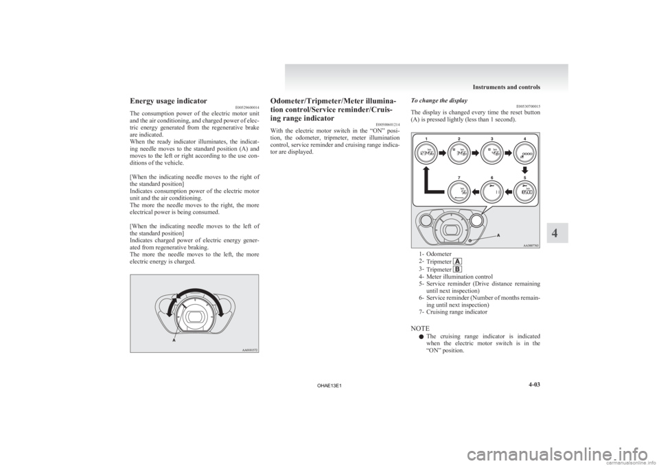
Energy usage indicator
E00529600014
The
consumption power of the electric motor unit
and the air conditioning, and charged power of elec-
tric energy generated from the regenerative brake
are indicated.
When the ready indicator illuminates, the indicat-
ing needle moves to the standard position (A) and
moves to the left or right according to the use con-
ditions of the vehicle.
[When the indicating needle moves to the right of
the standard position]
Indicates consumption power of the electric motor
unit and the air conditioning.
The more the needle moves to the right, the more
electrical power is being consumed.
[When the indicating needle moves to the left of
the standard position]
Indicates charged power of electric energy gener-
ated from regenerative braking.
The more the needle moves to the left, the more
electric energy is charged. Odometer/Tripmeter/Meter illumina-
tion control/Service reminder/Cruis-
ing range indicator
E00500601214
With
the electric motor switch in the “ON” posi-
tion, the odometer, tripmeter, meter illumination
control, service reminder and cruising range indica-
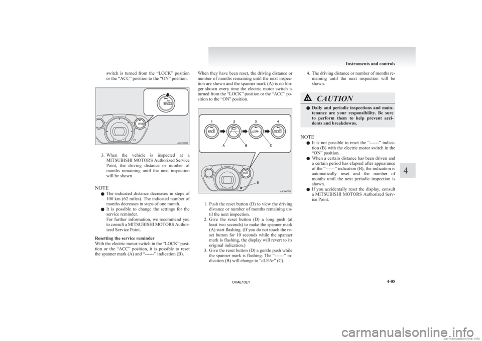
tor are displayed. To change the display
E00530700015
The
display is changed every time the reset button
(A) is pressed lightly (less than 1 second). 1- Odometer
2-
Tripmeter 3-
Tripmeter 4- Meter illumination control
5- Service
reminder (Drive distance remaining
until next inspection)
6- Service reminder (Number of months remain- ing until next inspection)
7- Cruising range indicator
NOTE l The cruising range indicator is indicated
when the electric motor switch is in the
“ON” position. Instruments and controls
4-03 4
OHAE13E1
Page 105 of 258

switch is turned from the “LOCK” position
or the “ACC” position to the “ON” position.
3. When the vehicle is inspected at a
MITSUBISHI MOTORS Authorized Service
Point, the driving distance or number of
months remaining until the next inspection
will be shown.
NOTE l The indicated distance decreases in steps of
100 km (62 miles). The indicated number of
months decreases in steps of one month.
l It is possible to change the settings for the
service reminder.
For further information, we recommend you
to consult a MITSUBISHI MOTORS Author-
ized Service Point.
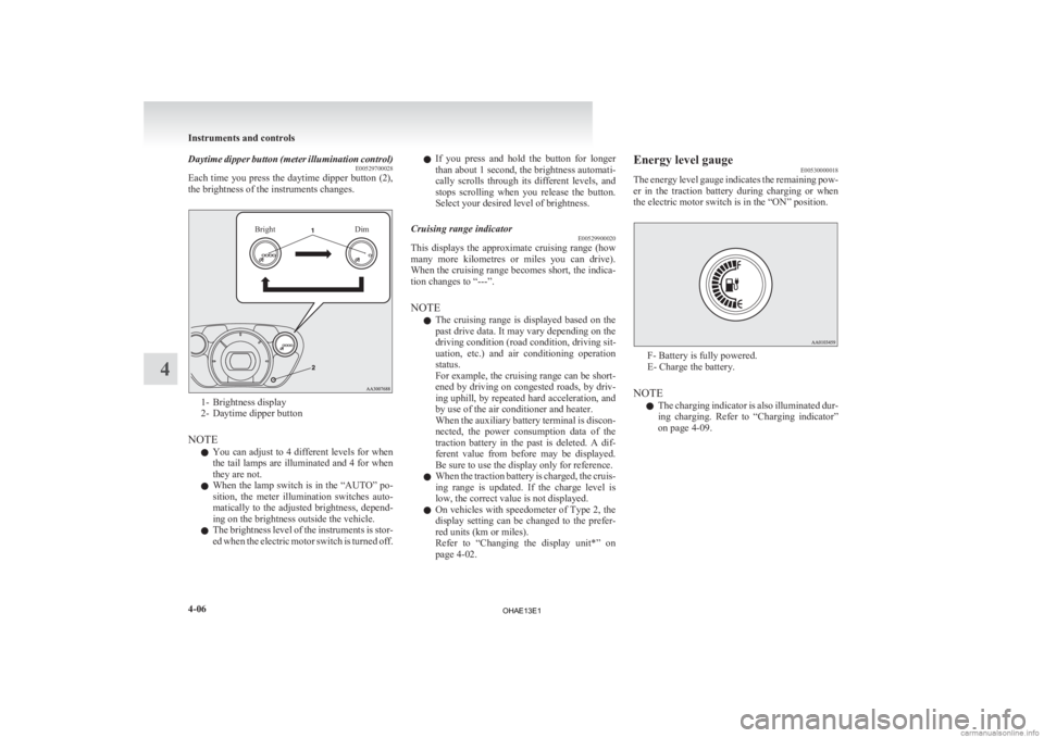
Resetting the service reminder
With the electric motor switch in the “LOCK” posi-
tion or the “ACC” position, it is possible to reset
the spanner mark (A) and “------” indication (B). When they have been reset, the driving distance or
number
of months remaining until the next inspec-
tion are shown and the spanner mark (A) is no lon-
ger shown every time the electric motor switch is
turned from the “LOCK” position or the “ACC” po-
sition to the “ON” position. 1. Push
the reset button (D) to view the driving
distance or number of months remaining un-
til the next inspection.
2. Give the reset button (D) a long push (at least two seconds) to make the spanner mark
(A) start flashing. (If you do not touch the re-
set button for 10 seconds while the spanner
mark is flashing, the display will revert to its
original indication.)
3. Give the reset button (D) a gentle push while the spanner mark is flashing. The “------” in-
dication (B) will change to “cLEAr” (C). 4. The
driving distance or number of months re-
maining until the next inspection will be
shown. CAUTION
l
Daily
and periodic inspections and main-
tenance are your responsibility. Be sure
to perform them to help prevent acci-
dents and breakdowns.
NOTE l It
is not possible to reset the “------” indica-
tion (B) with the electric motor switch in the
“ON” position.
l When a certain distance has been driven and
a certain period has elapsed after appearance
of the “------” indication (B), the indication is
automatically reset and the number of
months until the next periodic inspection is
shown.
l If you accidentally reset the display, consult
a MITSUBISHI MOTORS Authorized Serv-
ice Point. Instruments and controls
4-05 4
OHAE13E1
Page 106 of 258

Daytime dipper button (meter illumination control)
E00529700028
Each
time you press the daytime dipper button (2),
the brightness of the instruments changes.
Bright Dim1- Brightness display
2-
Daytime dipper button
NOTE l You can adjust to 4 different levels for when
the tail lamps are illuminated and 4 for when
they are not.
l When the lamp switch is in the “AUTO” po-
sition, the meter illumination switches auto-
matically to the adjusted brightness, depend-
ing on the brightness outside the vehicle.
l The brightness level of the instruments is stor-
ed when the electric motor switch is turned off. l
If
you press and hold the button for longer
than about 1 second, the brightness automati-
cally scrolls through its different levels, and
stops scrolling when you release the button.
Select your desired level of brightness.
Cruising range indicator E00529900020
This displays the approximate cruising range (how
many
more kilometres or miles you can drive).
When the cruising range becomes short, the indica-
tion changes to “---”.
NOTE
l The cruising range is displayed based on the
past drive data. It may vary depending on the
driving condition (road condition, driving sit-
uation, etc.) and air conditioning operation
status.
For example, the cruising range can be short-
ened by driving on congested roads, by driv-
ing uphill, by repeated hard acceleration, and
by use of the air conditioner and heater.
When the auxiliary battery terminal is discon-
nected, the power consumption data of the
traction battery in the past is deleted. A dif-
ferent value from before may be displayed.
Be sure to use the display only for reference.
l When the traction battery is charged, the cruis-
ing range is updated. If the charge level is
low, the correct value is not displayed.
l On vehicles with speedometer of Type 2, the
display setting can be changed to the prefer-
red units (km or miles).
Refer to “Changing the display unit*” on
page 4-02. Energy level gauge
E00530000018
The
energy level gauge indicates the remaining pow-
er in the traction battery during charging or when
the electric motor switch is in the “ON” position. F- Battery is fully powered.
E- Charge the battery.
NOTE l The
charging indicator is also illuminated dur-
ing charging. Refer to “Charging indicator”
on page 4-09. Instruments and controls
4-06
4
OHAE13E1
Page 113 of 258

Daytime running lamp*
E00530600014
The
daytime running lamps come on when the
ready indicator illuminates and the lamp switch is
in the “OFF” or “AUTO” position and the tail
lamps are off.
Dipper (High/Low beam change) E00506200329
When the lamp switch is in the “ ”
position, the
beam changes from high to low (or low to high)
each time the lever is pulled fully (1). While the high-
beam is on, the high-beam indication lamp in the in-
strument cluster will also illuminate. Headlamp flasher
E00506300199
The high-beams flash when the lever is pulled slight-
ly (2), and will go off when it is released.
When
the high-beam is on, the high-beam indica-
tion lamp in the instrument cluster will illuminate.
NOTE
l The high-beams can also flash when the
lamp switch is OFF. l
If
you turn the lamps off with the headlamps
set to high-beam, the headlamps are automat-
ically returned to their low-beam setting
when the lamp switch is next turned to the
“ ” position.
Headlamp levelling switch
E00506400839
The
angle of the headlamp beam varies depending
on the load carried by the vehicle.
The headlamp levelling switch can be used to ad-
just the headlamp illumination distance (when the
lower beam is illuminated) so that the headlamps’
glare does not distract other drivers.
Set the switch according to the following table. CAUTION
l
Always
perform adjustments before driv-
ing.
Do not attempt to adjust while driving, as
it could cause an accident. Instruments and controls
4-13 4
OHAE13E1
Page 114 of 258

NOTE
l When
adjusting the beam position, first put
the dial in the “0” position (the highest beam
position).
Except for vehicles with only the front
seats Vehi-
cle
condi- tion Switch
posi-tion “0” “0” “1” “1” “2” •: 1 person
:Full luggage loading
Switch position 0- Driver only/Driver + 1 front passenger
Switch position 1- 4 passengers (including driv- er)/
4
passengers (including driv-
er) + Full luggage loading
Switch position 2- Driver + Full luggage loading
Vehicles with only the front seats Vehicle condi-
tion Switch position “0”
“1”•: 1 person :Full luggage loading
Switch position 0- Driver only
Switch position 1- Driver + Full luggage loading Turn-signal lever
E00506501459 1- Turn-signals
When
making a normal turn, use position
(1). The lever will return automatically when
cornering is completed.
2- Lane-change signals When moving the lever to (2) slightly to
change a lane, the turn-signal lamps and indi-
cation lamp in the instrument cluster will on-
ly flash while the lever is operated.
Also, when you move the lever to (2) slight-
ly then release it, the turn-signal lamps and in-
dication lamp in the instrument cluster will
flash 3 times.
NOTE l If the lamp flashes unusually quickly, the
bulb in a turn-signal lamp may have burned
out. We recommend you to have the vehicle
inspected.
l It is possible to activate the following func-
tions. For further information, we recom-
mend you to consult a MITSUBISHI
MOTORS Authorized Service Point. Instruments and controls
4-14
4
OHAE13E1
Page 115 of 258

• Flashing of the turn-signal lamps when
the lever is operated with the electric mo-
tor switch in the “ACC” position
• The turn-signal lamps 3-flash function for lane changes can be deactivated.
• The time required to operate the lever for the 3-flash function can be adjusted. Hazard warning flasher switch
E00506600958
Use
the hazard warning flasher switch when the ve-
hicle has to be parked on the road for any emergency.
The hazard warning flashers can always be operat-
ed, regardless of the position of the electric motor
switch.
Push the switch to turn on the hazard warning flash-
ers, all turn-signal lamps flash continuously. To
turn them off, push the switch again. NOTE
l If
the switch is used for a long period while
the ready indicator is not illuminated, the aux-
iliary battery could go flat and it could be im-
possible to start the electric motor unit. Fog lamp switch
E00506700034
Front fog lamp switch* E00508300685
The front fog lamps can be operated while the head-
lamps
or tail lamps are on. Turn the knob in the
“ON” direction to turn on the front fog lamps. An
indication lamp in the instrument cluster will also
come on. Turn the knob in the “OFF” direction to
turn off the front fog lamps. The knob will automat-
ically return to its original position when you re-
lease it. NOTE
l The
front fog lamps are automatically turned
off when the headlamps or tail lamps are
turned off. To turn the front fog lamps on
again, turn the knob in the “ON” direction af-
ter turning on the headlamps or tail lamps.
l Do not use fog lamps except in conditions of
fog, otherwise excessive lamp glare may tem-
porarily blind oncoming vehicle drivers. Instruments and controls
4-15 4
OHAE13E1