2013 MERCEDES-BENZ B-CLASS SPORTS tow bar
[x] Cancel search: tow barPage 20 of 336
Average weight of the vehicle
occupants (definition)
....................309
Bar (definition) ............................... 309
Changing awheel .......................... 312
Characteristics .............................. 309
Checking ........................................ 293
Definition of terms .........................309
Direction of rotatio n...................... 312
Display message ............................ 214
Distributio nofthe vehicle
occupants (definition) ....................311
DOT, Tire Identification Number
(TIN) .............................................. .308
DOT (Department of
Transportation) (definition) ............309
GAWR (Gross Axle Weight Rating)
(definition) ..................................... 310
GVW (Gross Vehicle Weight)
(definition) ..................................... 310
GVWR (Gross Vehicle Weight
Rating) (definition) .........................310
Important safety notes ..................292
Increased vehicle weight due to
optional equipment (definition) ......309
Kilopascal (kPa) (definition) ...........310
Labeling (overview). .......................305
Load bearing index (definition) ......311
Load index ..................................... 308
Load index (definition) ...................310
M+S tires ....................................... 294
Maximum loaded vehicle weight
(definition) ..................................... 310
Maximum load on a tire
(definition) ..................................... 310
Maximum permissible tire
pressure (definition) ....................... 310
Maximum tire load. ........................303
Maximum tire load (definition) .......310
MOExtended tires ..........................294
Optional equipment weight
(definition) ..................................... 311
PSI (pounds per square inch)
(definition) ..................................... 310
Replacing ....................................... 312
Service life ..................................... 294
Sidewall (definition) .......................311
Speed rating (definition) ................310
Storing ........................................... 312Structure and characteristics
(definition)
..................................... 309
Summer tires ................................. 294
Temperature .................................. 305
TIN (Tire Identification Number)
(definition) ..................................... 311
Tire bead( definition) ...................... 311
Tire pressure (definition) ................311
Tire pressures (recommended )...... 309
Tire size (data) ............................... 316
Tire size designation, load-bearing
capacity, speed rating .................... 306
Tire tread ....................................... 293
Tire tread (definition) .....................311
Total load limit (definition) .............311
Traction ......................................... 304
Traction (definition) .......................311
Trea dwear ..................................... 304
Uniform Tire Quality Grading
Standard s...................................... 304
Uniform Tire Quality Grading
Standard s(definition) .................... 309
Unladen weight (definition) ............310
Wea rindicato r(definition) .............311
Whee lrim (definition ).................... 309
see Flat tire
Top Tether ............................................ 52
Towing Important safety guidelines ...........285
Installing the towing eye ................286
Removing the towing eye. ..............286
Towing away
With both axles on the ground .......286
With front axle raised ..................... 286
Tow-starting
Emergency engine starting ............287
Important safety notes ..................285
Installing the towing eye ................286
Removing the towing eye. ..............286
Traction control ................................... 63
Transmission see Automatic transmission
Transmission position display .........133
Transporting the vehicle ..................287
Trim pieces (cleaning instructions) .270
Trip computer (on-board
computer) .......................................... 182 Index
17
Page 172 of 336
Activating/deactivating the rea
rview
camera X
To activate: make sure that the SmartKey
is in position 2in the ignition lock.
X Make sure that in the audio system/
COMAND, the "Activation by R gear"
function is selected; see the separate
operating instructions for the audio
system/COMAND.
X Engage reverse gear.
Guide lines are used to show the area
behind the vehicle in the Audio/COMAND
display.
To deactivate: the rear view camera is
deactivated if you:
R selec ttransmission position P(vehicles
with automatic transmission)
R drive forward ten meters
R shift the transmission from Rto another
position (after 15 seconds)
R drive forwards at a speed of over 5mph
(10km/h)
Displays in the Audio/COMAND display The rear view camera may show a distorted
view of obstacles, show them incorrectly or
not at all. The rear view camera does not show
objects in the following positions:
R
very close to the rear bumper
R under the rear bumper
R in the area immediately above the tailgate
handle
! Objects not at ground level may appear to
be further away than they actually are, e.g.:
R the bumper of a parked vehicle
R the drawbar of a trailer
R the ball coupling of a trailer tow hitch
R the rear section of an HGV
R a slanted post
Use the guidelines only for orientation.
Approach objects no further than the
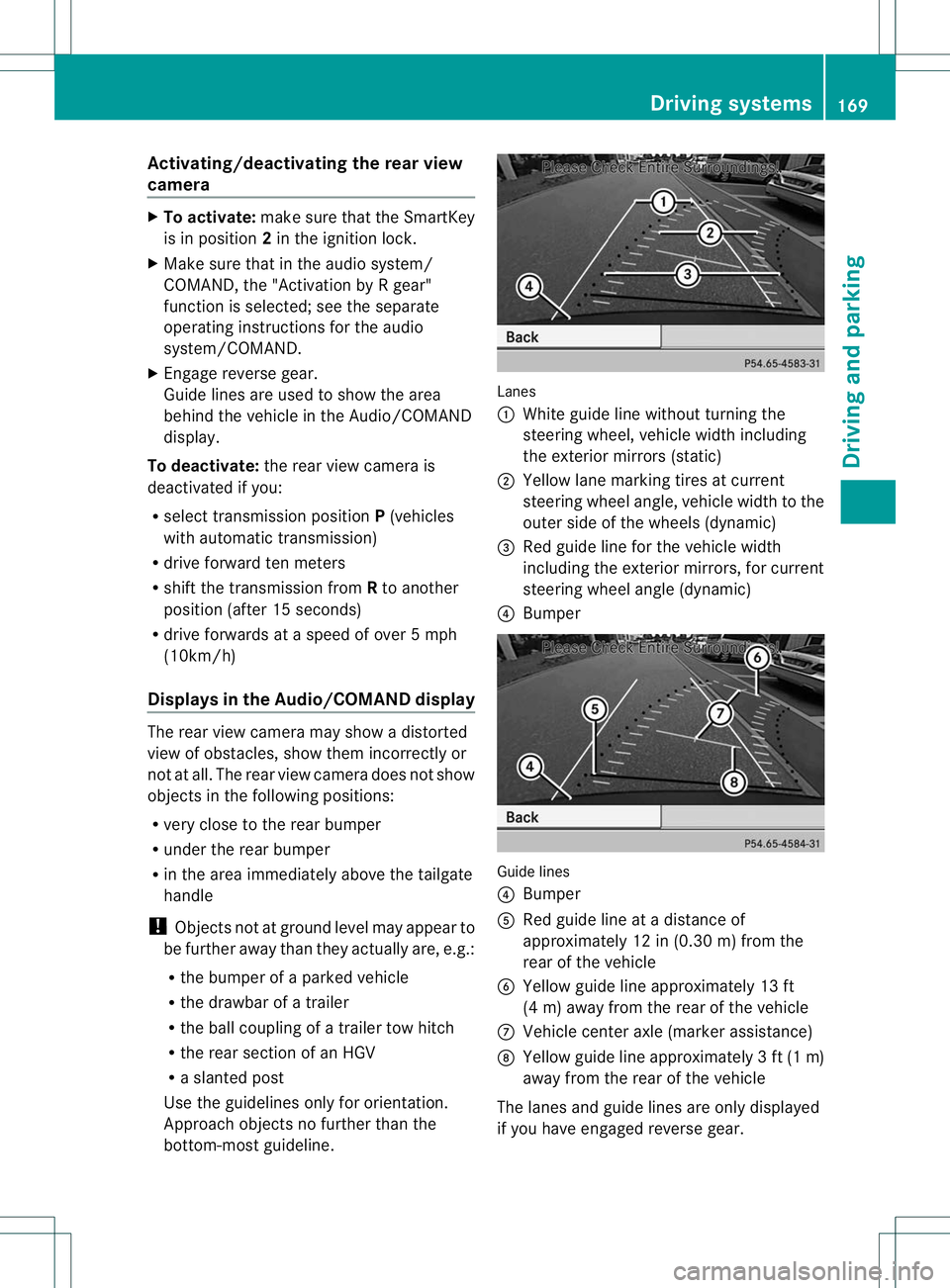
bottom-most guideline. Lanes
:
White guide line without turning the
steering wheel, vehicle width including
the exterior mirrors (static)
; Yellow lane marking tires at current
steering wheel angle, vehicle width to the
outer side of the wheels (dynamic)
= Red guide line for the vehicle width
including the exterior mirrors, for current
steering wheel angle (dynamic)
? Bumper Guide lines
?
Bumper
A Red guide line at a distance of
approximately 12 in (0.30 m) from the
rear of the vehicle
B Yellow guide line approximately 13 ft
(4 m) away from the rear of the vehicle
C Vehicle center axle (marker assistance)
D Yellow guide line approximately 3ft(1m)
away from the rear of the vehicle
The lanes and guide lines are only displayed
if you have engaged revers egear. Driving systems
169Driving and parking Z
Page 278 of 336
X
Open the tailgate.
X Lift the cargo compartment floor up
(Y page 239).
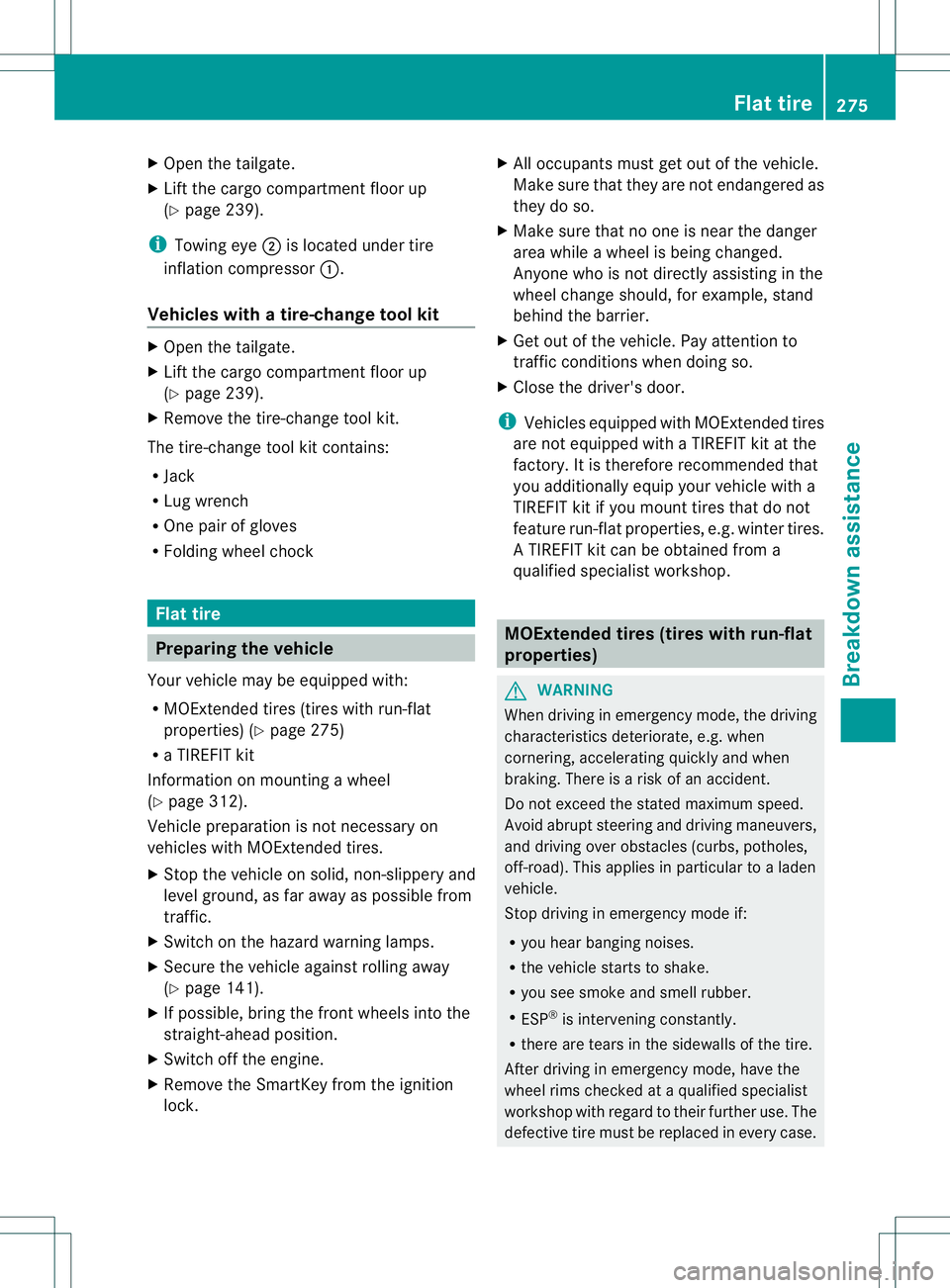
i Towing eye ;is located under tire
inflation compressor :.
Vehicles with atire-change tool kit X
Open the tailgate.
X Lift the cargo compartment floor up
(Y page 239).
X Remove the tire-change toolk it.
The tire-change tool kit contains:
R Jack
R Lug wrench
R One pair of gloves
R Folding wheel chock Flat tire
Preparing the vehicle
Your vehicle may be equipped with:
R MOExtended tires (tires with run-flat
properties) (Y page 275)
R a TIREFIT kit
Information on mounting a wheel
(Y page 312).
Vehicle preparation is not necessary on
vehicles with MOExtended tires.
X Stop the vehicle on solid, non-slippery and
level ground, as far away as possible from
traffic.
X Switch on the hazard warning lamps.
X Secure the vehicle against rolling away
(Y page 141).
X If possible, bring the front wheels into the
straight-ahead position.
X Switch off the engine.
X Remove the SmartKey from the ignition
lock. X
All occupants must get out of the vehicle.
Make sure that they are not endangered as
they do so.
X Make sure that no one is near the danger
area while a wheel is being changed.
Anyone who is not directly assisting in the
wheel change should, for example, stand
behind the barrier.
X Get out of the vehicle. Pay attention to
traffic conditions when doing so.
X Close the driver's door.
i Vehicles equipped with MOExtended tires
are not equipped with a TIREFIT kit at the
factory. It is therefore recommended that
you additionally equip your vehicle with a
TIREFIT kit if you mount tires that do not
feature run-flat properties, e.g. winter tires.
A TIREFIT kit can be obtained from a
qualified specialist workshop. MOExtended tires (tires with run-flat
properties)
G
WARNING
When driving in emergency mode, the driving
characteristics deteriorate, e.g. when
cornering, accelerating quickly and when
braking. There is a risk of an accident.
Do not exceed the stated maximum speed.
Avoid abrupt steering and driving maneuvers,
and driving over obstacles (curbs, potholes,
off-road). This applies in particular to a laden
vehicle.
Stop driving in emergency mode if:
R you hear banging noises.
R the vehicle starts to shake.
R you see smoke and smell rubber.
R ESP ®
is intervening constantly.
R there are tears in the sidewalls of the tire.
After driving in emergency mode, have the
wheel rims checked at a qualified specialist
workshop with regard to their further use. The
defective tire must be replaced in every case. Flat tire
275Breakdown assistance Z
Page 280 of 336
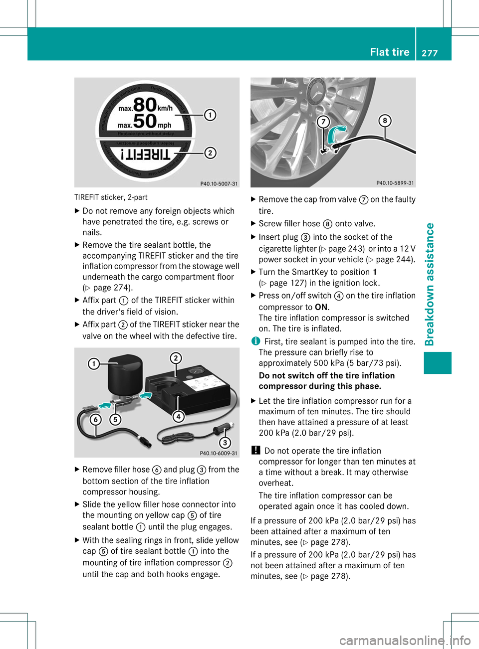
TIREFIT sticker, 2-part
X
Do not remove any foreign objects which
have penetrated the tire, e.g. screws or
nails.
X Remove the tire sealant bottle, the
accompanying TIREFIT sticker and the tire
inflation compressor from the stowage well
underneath the cargo compartment floor
(Y page 274).
X Affix part :of the TIREFIT sticker within
the driver's field of vision.
X Affix part ;of the TIREFIT sticker near the
valve on the wheel with the defective tire. X
Remove filler hose Band plug =from the
bottom section of the tire inflation
compressor housing.
X Slide the yellow filler hose connector into
the mounting on yellow cap Aof tire
sealant bottle :until the plug engages.
X With the sealing rings in front, slide yellow
cap Aof tire sealant bottle :into the
mounting of tire inflation compressor ;
until the cap and both hooks engage. X
Remove the cap from valve Con the faulty
tire.
X Screw filler hose Donto valve.
X Insert plug =into the socket of the
cigarette lighter (Y page 243) or into a 12 V
power socket in your vehicle (Y page 244).
X Turn the SmartKey to position 1
(Y page 127) in the ignition lock.
X Press on/offs witch?on the tire inflation
compressor to ON.
The tire inflatio ncompressor is switched
on. The tire is inflated.
i First, tire sealant is pumped into the tire.
The pressure can briefly rise to
approximately 500 kPa (5 bar/73 psi).
Do not switch off the tire inflation
compressor during this phase.
X Let the tire inflation compressor run for a
maximum of ten minutes. The tire should
then have attained a pressure of at least
200 kPa (2.0 bar/29 psi).
! Do not operate the tire inflation
compressor for longer than ten minutes at
a time without a break. It may otherwise
overheat.
The tire inflation compressor can be
operated again once it has cooled down.
If ap ressure of 200 kPa (2.0 bar/ 29 psi) has
been attained after a maximum of ten
minutes, see (Y page 278).
If ap ressure of 200 kPa (2.0 bar/ 29 psi) has
not been attained after a maximum of ten
minutes, see (Y page 278). Flat tire
277Breakdown assistance Z
Page 281 of 336
i
If tire sealant leaks out, allow it to dry. It
can then be removed like a layer of film.
If yourc lothes are soiled with tire sealant,
have the mcleaned with perchloroethylene
at a dry cleaner as soon as possible.
Tire pressure not reached If
ap ressure of 200 kPa (2.0 bar/ 29 psi) has
not been achieved after ten minutes:
X Switch off the tire inflation compressor.
X Unscrew the filler hose from the valve of
the faulty tire.
X Very slowly drive forwards or reverse
approximately 30 ft (10 m).
X Pump up the tire again.
After a maximum of ten minutes, the tire
pressure must be at least 200 kPa (2.0 bar/
29 psi). G
WARNING
If the required tire pressure is not reached
after the specified time, the tire is too badly
damaged. The tire sealant cannot repair the
tire in this instance. Damaged tires and a tire
pressure that is too low can significantly
impair the vehicle's braking and driving
characteristics. There is a risk of accident.
Do not continue driving. Contact a qualified
specialist workshop.
Tire pressure reached G
WARNING
At ire temporarily sealed with tire sealant
impairs the driving characteristics and is not
suitable for higher speeds. There is a risk of
accident.
You should therefore adapt your driving style
accordingly and drive carefully. Do not exceed
the specified maximum speed with a tire that
has been repaired using tire sealant.
! After use, excess tire sealant may run out
of the filler hose. This could cause stains. Therefore, place the filler hose in the plastic
bag that contained the TIREFIT kit. H
Environmental note
Have the used tire sealant bottle disposed of
professionally, e.g. at aqualified specialist
workshop.
If ap ressure of 200 kPa (2.0 bar/ 29 psi) has
been attained after a maximum of ten
minutes:
X Switch off the tire inflation compressor.
X Unscrew the filler hose from the valve of
the faulty tire.
X Stow the tire sealant bottle and the tire
inflation compressor.
X Pull away immediately.
The maximu mspeed for atire treated with tire
sealant is 50 mph (80k m/h). The upper part
of the TIREFIT sticker must be affixed to the
instrument cluster in the driver's field of
vision.
X Stop after driving for approximately ten
minutes and check the tire pressure with
the tire inflation compressor.
The tire pressure must now be at least
130 kPa (1.3 bar/19 psi). G
WARNING
If the required tire pressure is not reached
after driving for a short period, the tire is too
badly damaged. The tire sealant cannot repair
the tire in this instance. Damaged tires and a
tire pressure that is too low can significantly
impair the vehicle's braking and driving
characteristics. There is a risk of accident.
Do not continue driving. Contact a qualified
specialist workshop.
X Correct the tire pressure if it is still at least
130 kPa (1.3 bar/19 psi) (for the values,
see the Tire and Loading Information
placard on the driver's side B-pillar or tire
pressure table on the fuel filler flap).
X To increase the tire pressure: switch on
the tire inflation compressor. 278
Flat tireBreakdown assistance
Page 288 of 336
X
Close cover :of positive terminal ;after removing the jumper cables.
X Have the battery checked at a qualified specialist workshop.
i Jump-starting is no tconsidered to be a normal operating condition.
i Jumper cables and further information regarding jump starting can be obtained at any
qualified specialist workshop. Towing and tow-starting
Important safety notes
G
WARNING
Functions relevant to safety are restricted or
no longer available if:
R the engine is not running.
R the brake system or the power steering is
malfunctioning.
R there is a malfunction in the voltage supply
or the vehicle's electrical system.
If your vehicle is being towed, much more
force may be necessary to steer or brake.
There is a risk of an accident.
In such cases, use a tow bar. Before towing,
make sure that the steering moves freely. G
WARNING
If the weight of the vehicle to be towed or tow-
started is greater than the permissible gross
weight of your vehicle:
R the towing eye could detach itself
R the vehicle/trailer combination could
rollover.
There is a risk of an accident.
When towing or tow-starting another vehicle,
its weight should not be greater than the
permissible gross weight of your vehicle.
Information on your vehicle's gross vehicle
weight rating can be found on the vehicle
identification plate (Y page 323).G
WARNING
The vehicle is braked if the HOLD function is
activated. Therefore, deactivate HOLD if the
vehicle is to be towed. !
Only secure the tow rope or tow bar at the
towing eyes. Otherwise, the vehicle could
be damaged.
! Do not use the towing eye for recovery,
as this could damage the vehicle. If in
doubt, recover the vehicle with a crane.
! When towing, pull away slowly and
smoothly. If the tractive power is too high,
the vehicles could be damaged.
! The vehicle can be towed a maximum of
30 miles (50km). The towing speed of
30 mph (50km/h) must not be exceeded.
If the vehicle has to be towed more than
30 miles (50km), the front axle must be
raised or the entire vehicle raised and
transported.
! Do not tow with sling-type equipment.
This could damage the vehicle.
! Vehicles with automatic transmission
must not be started by tow-starting. This
could otherwise damage the transmission.
It is better to have the vehicle transported
than to have it towed.
When towing a vehicle, the transmission must
be in position N.
The battery must be connected and charged.
Otherwise, you:
R cannot turn the SmartKey to position 2in
the ignition lock
R cannot shift the transmission to position
N.
i Deactivate the automatic locking feature
(Y page 191). You could otherwise be
locked out when pushing or towing the
vehicle. Towing and tow-starting
285Breakdown assistance Z
Page 319 of 336
X
Place the ratchet wrench onto the hexagon
nut of the jack so that the letters ABare
visible.
X Turn the ratchet wrench until the vehicle is
once again standing firmly on the ground.
X Place the jack to one side.
X Tighten the wheel bolts evenly in a
crosswise patter ninthe sequence
indicated ( :toA). The tightening torque
must be 96 lb-ft (130 Nm).
X Turn the jack back to its initial position.
X Stow the jack and the rest of the vehicle
tools in the vehicle again.
X Check the tire pressure of the newly
installed wheel and adjust it if necessary.
Observe the recommended tire pressure
(Y page 295). Wheel and tire combinations
General notes
! For safety reasons, Mercedes-Benz
recommends that you only use tires and
wheels which have been approved by
Mercedes-Benzs pecifically for your
vehicle.
These tires have been specially adapted for
use with the control systems, such as ABS
or ESP ®
, and are marked as follows:
R MO =Mercedes-BenzO riginal
R MOE =Mercedes-BenzO riginal Extended
(tires featuring run-flat characteristics)
R MO1 =Mercedes-Benz Original (only
certain AMG tires)
Mercedes-BenzO riginal Extended tires
may only be used on wheels that have been
specifically approved by Mercedes-Benz.
Only use tires, wheels or accessories
tested and approved by Mercedes-Benz.
Certain characteristics, e.g. handling,
vehicle noise emissions or fuel
consumption, may otherwise be adversely
affected. In addition, when driving with a load, tire dimension variations could cause
the tires to come into contact with the
bodywork and axle components. This could
result in damage to the tires or the vehicle.
Mercedes-Benz accepts no liability for
damage resulting from the use of tires,
wheels or accessories other than those
tested and approved.
Information on tires, wheels and approved
combinations can be obtained from any
qualified specialist workshop.
! Retreaded tires are neither tested nor
recommended by Mercedes-Benz, since
previous damage cannot always be
detected on retreaded tires. As a result,
Mercedes-Benz cannot guarantee vehicle
safety if retreaded tires are mounted. Do
not mount used tires if you have no
information about their previous usage.
Overview of abbreviations usedint he
following tire tables:
R BA: both axles
R FA: front axle
R RA: rear axle
The recommended pressures for various
operating conditions can be found:
R on the Tire and Loading Information placard
with the recommended tire pressures on
the B-pillar on the driver's side
R in the tire pressure table on the inside of
the fuel filler flap
Observe the notes on recommended tire
pressures under various operating conditions
(Y page 295).
Check tire pressures regularly, and only when
the tires are cold. Comply with the
maintenance recommendations of the tire
manufacturer in the vehicle document wallet. 316
Wheel and tire combinationsWheels and tires