2013 MERCEDES-BENZ B-CLASS SPORTS towing
[x] Cancel search: towingPage 276 of 336
Useful information
............................274
Where will I find...? ...........................274
Flat tire .............................................. 275
Battery( vehicle)................................ 279
Jump-starting .................................... 283
Towing and tow-starting ..................285
Fuses .................................................. 287 273Breakdown assistance
Page 277 of 336
Useful information
i This Operator's Manual describes all
models and all standard and optional
equipment of your vehicle available at the
time of publication of the Operator's
Manual. Country-specific differences are
possible. Please note that your vehicle may
not be equipped with all features
described. This also applies to safety-
related systems and functions.
i Please read the information on qualified
specialist workshops (Y page 23).Where will I find...?
First-aid kit
X
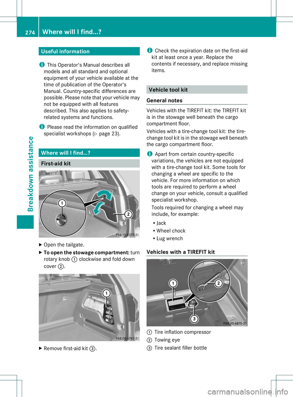
Open the tailgate.
X To open the stowage compartment: turn
rotary knob :clockwise and fold down
cover ;. X
Remove first-aid kit =. i
Check the expiration date on the first-aid
kit at least once a year. Replace the
contents if necessary, and replace missing
items. Vehicle tool kit
General notes Vehicles with the TIREFIT kit: the TIREFIT kit
is in the stowage well beneat
hthe cargo
compartment floor.
Vehicles with a tire-change tool kit: the tire-
change tool kit is in the stowage well beneath
the cargo compartment floor.
i Apart from certain country-specific
variations, the vehicles are not equipped
with a tire-change tool kit. Some tools for
changing a wheel are specific to the
vehicle. For more information on which
tools are required to perform a wheel
change on your vehicle, consult a qualified
specialist workshop.
Tools required for changing awheel may
include, for example:
R Jack
R Wheel chock
R Lug wrench
Vehicles with aTIREFIT kit :
Tire inflation compressor
; Towing eye
= Tire sealan tfiller bottle 274
Where will I find...?Breakdown assistance
Page 278 of 336
X
Open the tailgate.
X Lift the cargo compartment floor up
(Y page 239).
i Towing eye ;is located under tire
inflation compressor :.
Vehicles with atire-change tool kit X
Open the tailgate.
X Lift the cargo compartment floor up
(Y page 239).
X Remove the tire-change toolk it.
The tire-change tool kit contains:
R Jack
R Lug wrench
R One pair of gloves
R Folding wheel chock Flat tire
Preparing the vehicle
Your vehicle may be equipped with:
R MOExtended tires (tires with run-flat
properties) (Y page 275)
R a TIREFIT kit
Information on mounting a wheel
(Y page 312).
Vehicle preparation is not necessary on
vehicles with MOExtended tires.
X Stop the vehicle on solid, non-slippery and
level ground, as far away as possible from
traffic.
X Switch on the hazard warning lamps.
X Secure the vehicle against rolling away
(Y page 141).
X If possible, bring the front wheels into the
straight-ahead position.
X Switch off the engine.
X Remove the SmartKey from the ignition
lock. X
All occupants must get out of the vehicle.
Make sure that they are not endangered as
they do so.
X Make sure that no one is near the danger
area while a wheel is being changed.
Anyone who is not directly assisting in the
wheel change should, for example, stand
behind the barrier.
X Get out of the vehicle. Pay attention to
traffic conditions when doing so.
X Close the driver's door.
i Vehicles equipped with MOExtended tires
are not equipped with a TIREFIT kit at the
factory. It is therefore recommended that
you additionally equip your vehicle with a
TIREFIT kit if you mount tires that do not
feature run-flat properties, e.g. winter tires.
A TIREFIT kit can be obtained from a
qualified specialist workshop. MOExtended tires (tires with run-flat
properties)
G
WARNING
When driving in emergency mode, the driving
characteristics deteriorate, e.g. when
cornering, accelerating quickly and when
braking. There is a risk of an accident.
Do not exceed the stated maximum speed.
Avoid abrupt steering and driving maneuvers,
and driving over obstacles (curbs, potholes,
off-road). This applies in particular to a laden
vehicle.
Stop driving in emergency mode if:
R you hear banging noises.
R the vehicle starts to shake.
R you see smoke and smell rubber.
R ESP ®
is intervening constantly.
R there are tears in the sidewalls of the tire.
After driving in emergency mode, have the
wheel rims checked at a qualified specialist
workshop with regard to their further use. The
defective tire must be replaced in every case. Flat tire
275Breakdown assistance Z
Page 288 of 336
X
Close cover :of positive terminal ;after removing the jumper cables.
X Have the battery checked at a qualified specialist workshop.
i Jump-starting is no tconsidered to be a normal operating condition.
i Jumper cables and further information regarding jump starting can be obtained at any
qualified specialist workshop. Towing and tow-starting
Important safety notes
G
WARNING
Functions relevant to safety are restricted or
no longer available if:
R the engine is not running.
R the brake system or the power steering is
malfunctioning.
R there is a malfunction in the voltage supply
or the vehicle's electrical system.
If your vehicle is being towed, much more
force may be necessary to steer or brake.
There is a risk of an accident.
In such cases, use a tow bar. Before towing,
make sure that the steering moves freely. G
WARNING
If the weight of the vehicle to be towed or tow-
started is greater than the permissible gross
weight of your vehicle:
R the towing eye could detach itself
R the vehicle/trailer combination could
rollover.
There is a risk of an accident.
When towing or tow-starting another vehicle,
its weight should not be greater than the
permissible gross weight of your vehicle.
Information on your vehicle's gross vehicle
weight rating can be found on the vehicle
identification plate (Y page 323).G
WARNING
The vehicle is braked if the HOLD function is
activated. Therefore, deactivate HOLD if the
vehicle is to be towed. !
Only secure the tow rope or tow bar at the
towing eyes. Otherwise, the vehicle could
be damaged.
! Do not use the towing eye for recovery,
as this could damage the vehicle. If in
doubt, recover the vehicle with a crane.
! When towing, pull away slowly and
smoothly. If the tractive power is too high,
the vehicles could be damaged.
! The vehicle can be towed a maximum of
30 miles (50km). The towing speed of
30 mph (50km/h) must not be exceeded.
If the vehicle has to be towed more than
30 miles (50km), the front axle must be
raised or the entire vehicle raised and
transported.
! Do not tow with sling-type equipment.
This could damage the vehicle.
! Vehicles with automatic transmission
must not be started by tow-starting. This
could otherwise damage the transmission.
It is better to have the vehicle transported
than to have it towed.
When towing a vehicle, the transmission must
be in position N.
The battery must be connected and charged.
Otherwise, you:
R cannot turn the SmartKey to position 2in
the ignition lock
R cannot shift the transmission to position
N.
i Deactivate the automatic locking feature
(Y page 191). You could otherwise be
locked out when pushing or towing the
vehicle. Towing and tow-starting
285Breakdown assistance Z
Page 289 of 336
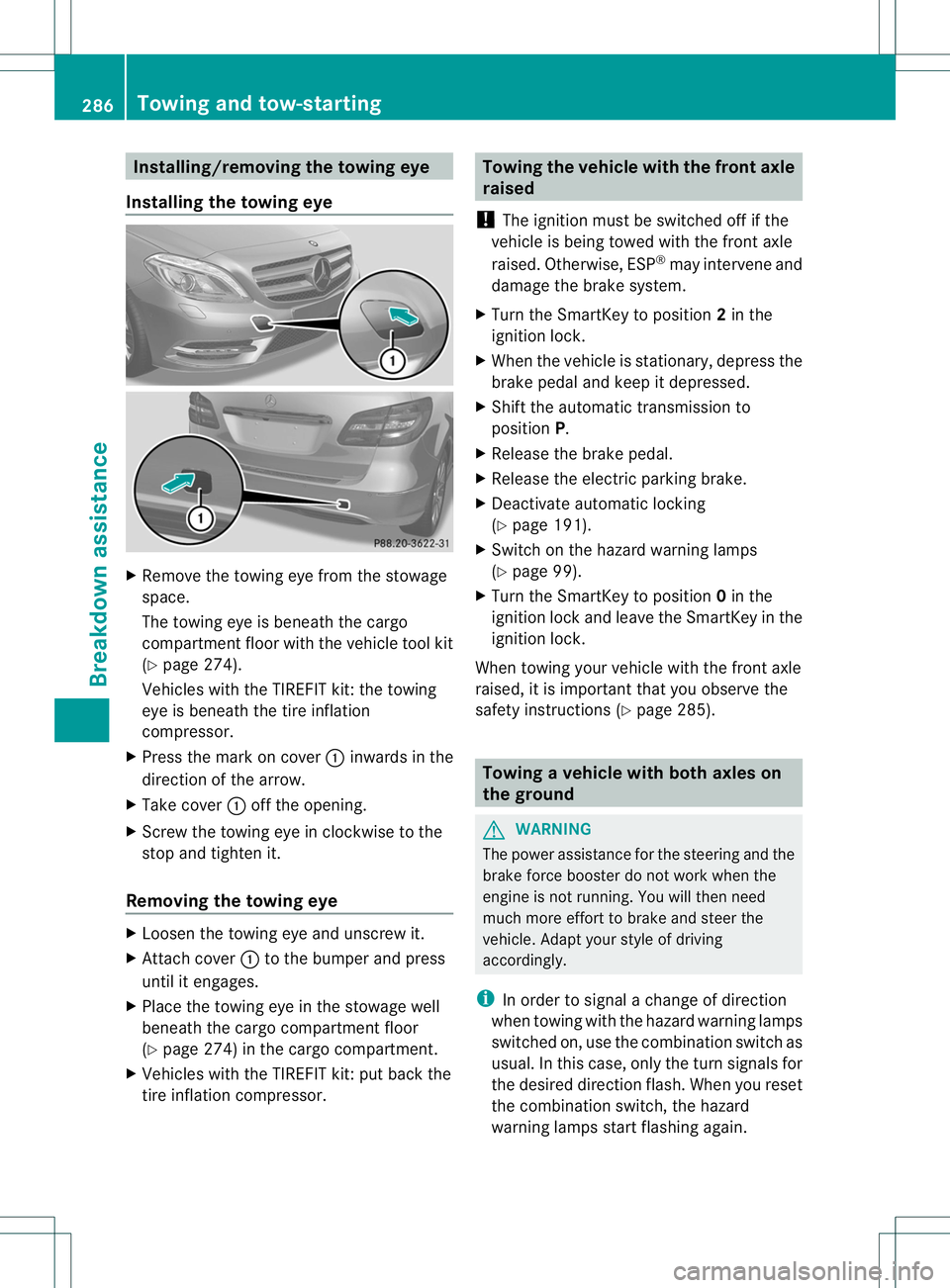
Installing/removing the towing eye
Installing the towing eye X
Remove the towing eye from the stowage
space.
The towing eye is beneath the cargo
compartmen tfloor with the vehicle tool kit
(Y page 274).
Vehicles with the TIREFIT kit :the towing
eye is beneath the tire inflation
compressor.
X Press the mark on cover :inwards in the
direction of the arrow.
X Take cover :off the opening.
X Screw the towing eye in clockwise to the
stop and tighten it.
Removing the towing eye X
Loosen the towing eye and unscrew it.
X Attach cover :to the bumper and press
until it engages.
X Place the towing eye in the stowage well
beneath the cargo compartmentf loor
(Y page 274) in the cargo compartment.
X Vehicles with the TIREFIT kit: put back the
tire inflation compressor. Towing the vehicle with the front axle
raised
! The ignition must be switched off if the
vehicle is being towed with the front axle
raised. Otherwise, ESP ®
may intervene and
damage the brake system.
X Turn the SmartKey to position 2in the
ignition lock.
X When the vehicle is stationary, depress the
brake pedal and keep it depressed.
X Shift the automatic transmission to
position P.
X Release the brake pedal.
X Release the electric parking brake.
X Deactivate automatic locking
(Y page 191).
X Switch on the hazard warning lamps
(Y page 99).
X Turn the SmartKey to position 0in the
ignition lock and leave the SmartKey in the
ignition lock.
When towing your vehicle with the front axle
raised, it is importan tthat you observe the
safety instructions (Y page 285). Towing
avehicle with both axles on
the ground G
WARNING
The power assistance for the steering and the
brake force booster do not work when the
engine is not running. You will then need
much more effort to brake and steer the
vehicle .Adapt your style of driving
accordingly.
i In order to signal a change of direction
when towing with the hazard warning lamps
switched on, use the combination switch as
usual. In this case, only the turn signals for
the desired direction flash. When you reset
the combination switch, the hazard
warning lamps start flashing again. 286
Towing and tow-startingBreakdown assistance
Page 290 of 336
The automatic transmission automatically
shifts to position
Pwhen you open the driver's
or front-passenger door or when you remove
the SmartKey from the ignition lock. In order
to ensure that the automatic transmission
stays in position Nwhen towing the vehicle,
you must observe the following points:
X Make sure that the vehicle is stationary.
X Turn the SmartKey to position 2in the
ignition lock.
X Depress and hold the brake pedal.
X Shift the automatic transmission to
position N.
X Leave the SmartKey in position 2in the
ignition lock.
X Release the brake pedal.
X Release the electric parking brake.
X Switch on the hazard warning lamps
(Y page 99).
It is importan tthat you observe the safety
instructions when towing away your vehicle
(Y page 285). Transporting the vehicle
! Only lash the vehicle down by the wheels
or wheel rims, not by parts of the vehicle
such as axle or steering components.
Otherwise, the vehicle could be damaged.
X Turn the SmartKey to position 2in the
ignition lock.
X Shift the transmission to position N.
As soon as the vehicle is loaded:
X Prevent the vehicle from rolling away by
applying the electric parking brake.
X Shift the transmission to position P.
X Turn the SmartKey to position 0in the
ignition lock and remove it.
X Secure the vehicle.
The towing eye can be used to pull the vehicle
onto a trailer or transporter for transporting
purposes. Tow-starting (emergency starting)
! Vehicles with automatic transmission
must not be tow-started. You could
otherwise damage the automatic
transmission.
When tow-starting, it is important that you
observe the safety instructions (Y page 285). Fuses
Important safety notes
G
WARNING
Only use fuses that have been approved for
Mercedes-Ben zvehicles and that have the
correct fuse rating for the systems
concerned. Do not attempt to repair or bridge
faulty fuses. Using fuses that have not been
approved or attempting to repair or bridge
faulty fuses could cause the fuse to be
overloaded and result in afire. Have the cause
traced and rectified at a qualified specialist
workshop.
! Only use fuses that have been approved
for Mercedes-Ben zvehicles and which
have the correct fuse rating for the system
concerned. Only use fuses marked with an
"S". Otherwise, components or systems
could be damaged.
The fuses in your vehicle serve to close down
faulty circuits. If afuse blows, all the
components on the circuit and their functions
stop operating.
Blown fuses must be replace dwith fuses of
the same rating, which you can recognize by
the color and value. The fuse ratings are listed
in the fuse allocation chart.
If a newly inserted fuse also blows, have the
cause traced and rectified at a qualified
specialist workshop, e.g. an authorized
Mercedes-Ben zCenter. Fuses
287Breakdown assistance Z
Page 304 of 336
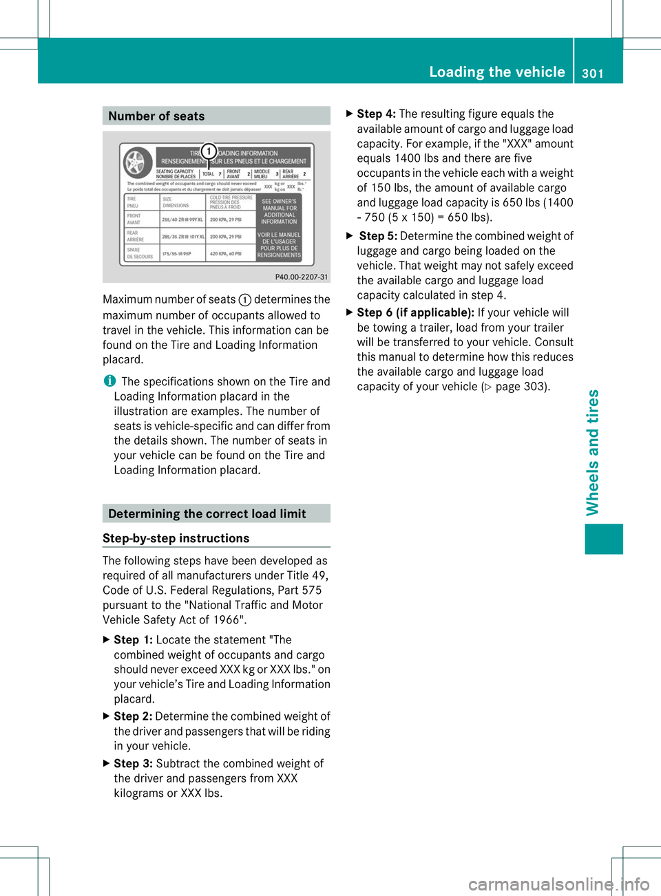
Number of seats
Maximum numbe
rofseats:determines the
maximum number of occupants allowed to
travel in the vehicle. This information can be
found on the Tire and Loading Information
placard.
i The specifications shown on the Tire and
Loading Information placard in the
illustration are examples. The number of
seats is vehicle-specific and can differ from
the details shown. The number of seats in
your vehicle can be found on the Tire and
Loading Information placard. Determining the correct load limit
Step-by-step instructions The following steps have been developed as
required of all manufacturers under Title 49,
Code of U.S.F
ederal Regulations, Part 575
pursuant to the "National Traffic and Motor
Vehicle Safety Act of 1966".
X Step 1: Locate the statement "The
combined weight of occupants and cargo
should never exceed XXX kg or XXX lbs." on
your vehicle’s Tire and Loading Information
placard.
X Step 2: Determine the combined weight of
the driver and passengers that will be riding
in your vehicle.
X Step 3: Subtract the combined weight of
the driver and passengers from XXX
kilograms or XXX lbs. X
Step 4: The resulting figure equals the
available amount of cargo and luggage load
capacity. For example, if the "XXX" amount
equals 1400l bs and there are five
occupants in the vehicle each with a weight
of 150 lbs, the amount of available cargo
and luggage load capacity is 650 lbs (1400
Ò 750 (5 x 150) = 650 lbs).
X Step 5: Determine the combined weight of
luggage and cargo being loaded on the
vehicle. That weight may not safely exceed
the available cargo and luggage load
capacity calculated in step 4.
X Step 6 (if applicable): If your vehicle will
be towing a trailer, load from your trailer
will be transferred to your vehicle. Consult
this manual to determine how this reduces
the available cargo and luggage load
capacity of your vehicle ( Ypage 303). Loading the vehicle
301Wheels and tires Z