2013 Lancia Voyager tire size
[x] Cancel search: tire sizePage 259 of 360

TIRE SAFETY
INFORMATION
Tire MarkingsNOTE:
P (Passenger) - Metric tire sizing
is based on U.S. design stan-
dards. P-Metric tires have the
letter “P” molded into the side-
wall preceding the size designa-
tion. Example: P215/65R15 95H.
European-Metric tire sizing is based on European design stan-
dards. Tires designed to this
standard have the tire size
molded into the sidewall begin-
ning with the section width. The
letter "P" is absent from this tire
size designation. Example: 215/
65R15 96H.
LT (Light Truck) - Metric tire sizing is based on U.S. design
standards. The size designation
for LT-Metric tires is the same as
for P-Metric tires except for the
letters “LT” that are molded into
the sidewall preceding the size
designation. Example:
LT235/85R16. Temporary spare tires are
spares designed for temporary
emergency use only. Temporary
high pressure compact spare
tires have the letter “T” or “S”
molded into the sidewall pre-
ceding the size designation. Ex-
ample: T145/80D18 103M.
High flotation tire sizing is based on U.S. design standards
and it begins with the tire diam-
eter molded into the sidewall.
Example: 31x10.5 R15 LT.1 — U.S. DOT
Safety Standards
Code (TIN) 4 — Maximum
Load
2 — Size Desig-
nation 5 — Maximum
Pressure
3 — Service De-
scription 6 — Treadwear,
Traction and
Temperature
Grades
253
Page 260 of 360

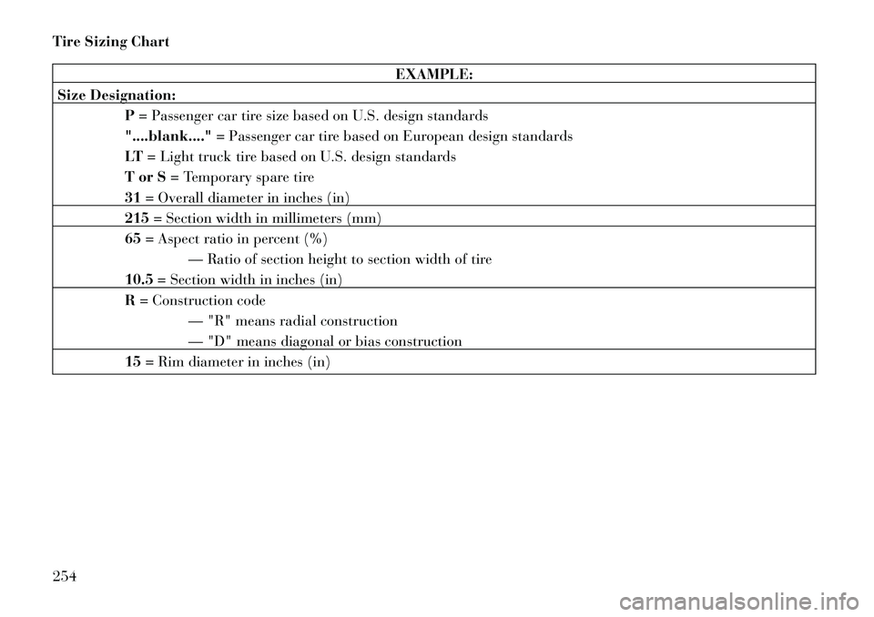
Tire Sizing Chart
EXAMPLE:
Size Designation: P= Passenger car tire size based on U.S. design standards
"....blank...." = Passenger car tire based on European design standards
LT = Light truck tire based on U.S. design standards
T or S = Temporary spare tire
31 = Overall diameter in inches (in)
215 = Section width in millimeters (mm)
65 = Aspect ratio in percent (%)
— Ratio of section height to section width of tire
10.5 = Section width in inches (in)
R = Construction code
— "R" means radial construction
— "D" means diagonal or bias construction
15 = Rim diameter in inches (in)
254
Page 262 of 360

Tire Identification Number
(TIN)
The TIN may be found on one or both
sides of the tire, however, the datecode may only be on one side. Tires
with white sidewalls will have the full
TIN, including the date code, located
on the white sidewall side of the tire.
Look for the TIN on the outboard sideof black sidewall tires as mounted on
the vehicle. If the TIN is not found on
the outboard side, then you will find it
on the inboard side of the tire.
EXAMPLE:
DOT MA L9 ABCD 0301
DOT = Department of Transportation
— This symbol certifies that the tire is in compliance with the U.S. Department of Transportation tire safety
standards and is approved for highway use
MA = Code representing the tire manufacturing location (two digits)
L9 = Code representing the tire size (two digits)
ABCD = Code used by the tire manufacturer (one to four digits)
03 = Number representing the week in which the tire was manufactured (two digits)
—03 means the 3rd week.
01 = Number representing the year in which the tire was manufactured (two digits)
—01 means the year 2001
— Prior to July 2000, tire manufacturers were only required to have one number to represent the year in
which the tire was manufactured. Example: 031 could represent the 3rd week of 1981 or 1991
256
Page 263 of 360

Tire Terminology And Definitions
TermDefinition
B-Pillar The vehicle B-Pillar is the structural member of the body located be-
hind the front door.
Cold Tire Inflation Pressure Cold tire inflation pressure is defined as the tire pressure after the ve-
hicle has not been driven for at least 3 hours, or driven less than 1
mile (1.6 km) after sitting for a three hour period. Inflation pressure is
measured in units of PSI (pounds per square inch) or kPa (kilopas-
cals).
Maximum Inflation Pressure The maximum inflation pressure is the maximum permissible cold tire
inflation pressure for this tire. The maximum inflation pressure is
molded into the sidewall.
Recommended Cold Tire Inflation Pres-
sure Vehicle manufacturer's recommended cold tire inflation pressure as
shown on the tire placard.
Tire Placard A paper label permanently attached to the vehicle describing the vehi-
cle’s loading capacity, the original equipment tire sizes and the recom-
mended cold tire inflation pressures.
257
Page 264 of 360

Tire Loading And Tire
Pressure
Tire And Loading Information
Placard Location
NOTE: The proper cold tire infla-
tion pressure is listed on the driv-
er’s side B-Pillar or the rear edge
of the driver's side door.Tire And Loading Information
Placard
This placard tells you important
information about the:
1) number of people that can be
carried in the vehicle
2) total weight your vehicle can
carry
3) tire size designed for your ve-
hicle
4) cold tire inflation pressures for
the front, rear, and spare tires.
Loading
The vehicle maximum load on the tire
must not exceed the load carrying ca-
pacity of the tire on your vehicle. You
will not exceed the tire's load carrying
capacity if you adhere to the loading
conditions, tire size, and cold tire in-
flation pressures specified on the Tire
and Loading Information placard and
in the “Vehicle Loading” section of
this manual. NOTE: Under a maximum loaded
vehicle condition, gross axle
weight ratings (GAWRs) for the
front and rear axles must not be
exceeded. For further information
on GAWRs, vehicle loading, and
trailer towing, refer to “Vehicle
Loading” in this section.
To determine the maximum loading
conditions of your vehicle, locate the
statement “The combined weight of
occupants and cargo should never ex-
ceed XXX lbs or XXX kg” on the Tire
and Loading Information placard.
The combined weight of occupants,
cargo/luggage and trailer tongue
weight (if applicable) should never
exceed the weight referenced here.
Tire Placard Location
258
Page 268 of 360

For example, your vehicle may have a
recommended cold (parked for more
than three hours) tire pressure of 2.4
BAR. If the ambient temperature is
20°C and the measured tire pressure
is 2.1 BAR, a temperature drop to
7°C will decrease the tire pressure to
approximately 1.8 BAR. This tire
pressure is sufficiently low enough to
turn on the “Tire Pressure Monitoring
Telltale Light.” Driving the vehicle
may cause the tire pressure to rise to
approximately 2.1 BAR, but the “Tire
Pressure Monitoring Telltale Light”
will still be on. In this situation, the
“Tire Pressure Monitoring Telltale
Light” will turn off only after the tires
have been inflated to the vehicle’s rec-
ommended cold tire pressure value.
CAUTION!
The TPMS has been optimizedfor the original equipment tires
and wheels. TPMS pressures have
been established for the tire size
equipped on your vehicle. Unde-
sirable system operation or sensor
damage may result when using
replacement equipment that is
not of the same size, type, and/or
style. Aftermarket wheels can
cause sensor damage. Do not use
aftermarket sealants or balance
beads if your vehicle is equipped
with a TPMS, as damage to the
sensors may result.
After inspecting or adjusting the tire pressure always reinstall the
valve stem cap. This will prevent
moisture and dirt from entering
the valve stem, which could dam-
age the TPMS sensor.
NOTE:
The TPMS is not intended to re- place normal tire care and
maintenance, or to provide
warning of a tire failure or con-
dition. The TPMS should not be used as
a tire pressure gauge while ad-
justing your tire pressure.
Driving on a significantly under- inflated tire causes the tire to
overheat and can lead to tire
failure. Under-inflation also re-
duces fuel efficiency and tire
tread life, and may affect the ve-
hicle’s handling and stopping
ability.
The TPMS is not a substitute for proper tire maintenance, and it
is the driver's responsibility to
maintain correct tire pressure,
using an accurate tire pressure
gage, even if under-inflation has
not reached the level to trigger
illumination of the “Tire Pres-
sure Monitoring Telltale Light.”
Seasonal temperature changes will affect tire pressure, and the
TPMS will monitor the actual
tire pressure in the tire.
262
Page 294 of 360

4. Raise the vehicle by turning the
jack screw to the right, using the
swivel wrench. Raise the vehicle only
until the tire just clears the surface
and enough clearance is obtained to
install the spare tire. Minimum tire lift
provides maximum stability.WARNING!
Raising the vehicle higher than nec-
essary can make the vehicle less
stable. It could slip off the jack and
hurt someone near it. Raise the ve-
hicle only enough to remove the
tire.
5. Remove the wheel lug nuts, for
vehicles with wheel covers, remove
the cover from the wheel by hand. Do
not pry the wheel cover off. Then pull
the wheel off the hub.
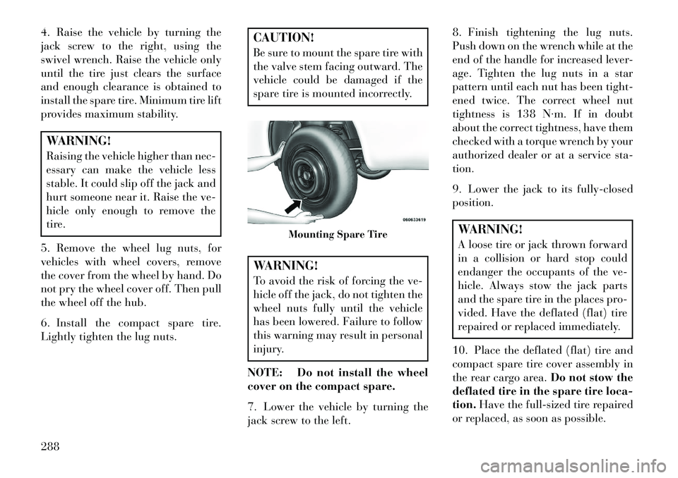
6. Install the compact spare tire.
Lightly tighten the lug nuts.
CAUTION!
Be sure to mount the spare tire with
the valve stem facing outward. The
vehicle could be damaged if the
spare tire is mounted incorrectly.WARNING!
To avoid the risk of forcing the ve-
hicle off the jack, do not tighten the
wheel nuts fully until the vehicle
has been lowered. Failure to follow
this warning may result in personal
injury.
NOTE: Do not install the wheel
cover on the compact spare.
7. Lower the vehicle by turning the
jack screw to the left. 8. Finish tightening the lug nuts.
Push down on the wrench while at the
end of the handle for increased lever-
age. Tighten the lug nuts in a star
pattern until each nut has been tight-
ened twice. The correct wheel nut
tightness is 138 N·m. If in doubt
about the correct tightness, have them
checked with a torque wrench by your
authorized dealer or at a service sta-
tion.
9. Lower the jack to its fully-closed
position.
WARNING!
A loose tire or jack thrown forward
in a collision or hard stop could
endanger the occupants of the ve-
hicle. Always stow the jack parts
and the spare tire in the places pro-
vided. Have the deflated (flat) tire
repaired or replaced immediately.
10. Place the deflated (flat) tire and
compact spare tire cover assembly in
the rear cargo area. Do not stow the
deflated tire in the spare tire loca-
tion. Have the full-sized tire repaired
or replaced, as soon as possible.
Mounting Spare Tire
288
Page 296 of 360

5. Continue to rotate the nut to the
right until you hear the winch mecha-
nism click three times. It cannot be
overtightened. Check under the ve-
hicle to ensure the compact spare tire/
cover assembly is positioned correctly
against the underside of the vehicle.CAUTION!
The winch mechanism is designed
specifically to stow a compact spare
tire only. Do not attempt to use the
winch to stow the full size flat tire,
or any other full-size tire. Vehicle
damage may result.
ROAD TIRE
INSTALLATION
Vehicles Equipped With Wheel
Covers
1. Mount the road tire on the axle.
2. To ease the installation process for
steel wheels with wheel covers, install
two lug nuts on the mounting studs
which are on each side of the valve
stem. Install the lug nuts with the cone
shaped end of the nut toward the
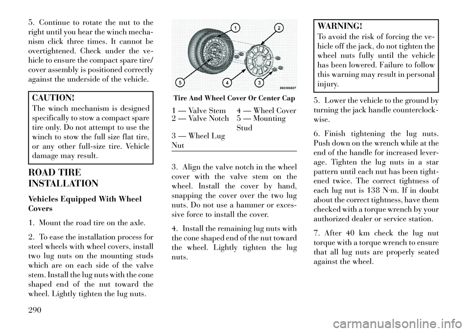
wheel. Lightly tighten the lug nuts. 3. Align the valve notch in the wheel
cover with the valve stem on the
wheel. Install the cover by hand,
snapping the cover over the two lug
nuts. Do not use a hammer or exces-
sive force to install the cover.
4. Install the remaining lug nuts with
the cone shaped end of the nut toward
the wheel. Lightly tighten the lug
nuts.
WARNING!
To avoid the risk of forcing the ve-
hicle off the jack, do not tighten the
wheel nuts fully until the vehicle
has been lowered. Failure to follow
this warning may result in personal
injury.
5. Lower the vehicle to the ground by
turning the jack handle counterclock-
wise.
6. Finish tightening the lug nuts.
Push down on the wrench while at the
end of the handle for increased lever-
age. Tighten the lug nuts in a star
pattern until each nut has been tight-
ened twice. The correct tightness of
each lug nut is 138 N·m. If in doubt
about the correct tightness, have them
checked with a torque wrench by your
authorized dealer or service station.
7. After 40 km check the lug nut
torque with a torque wrench to ensure
that all lug nuts are properly seated
against the wheel.
Tire And Wheel Cover Or Center Cap1 — Valve Stem 4 — Wheel Cover
2 — Valve Notch 5 — Mounting Stud
3 — Wheel Lug
Nut
290