Page 319 of 397

719
Maintenance
Vacuum crankcase ventilation hoses
Inspect the surface of hoses for evidence
of heat and/or mechanical damage. Hard
and brittle rubber, cracking, tears, cuts,
abrasions, and excessive swelling indi-
cate deterioration. Particular attention
should be paid to examine those hose
surfaces nearest to high heat sources,
such as the exhaust manifold. Inspect the hose routing to assure that the hoses do not come in contact with
any heat source, sharp edges or movingcomponent which might cause heat dam-
age or mechanical wear. Inspect all hose
connections, such as clamps and cou-
plings, to make sure they are secure, and
that no leaks are present. Hoses should
be replaced immediately if there is any
evidence of deterioration or damage.
Air cleaner filter
A Genuine HYUNDAI air cleaner filter isrecommended when the filter is replaced.
Spark plugs
Make sure to install new spark plugs of
the correct heat range.
Valve clearance
Inspect for excessive valve noise and/or
engine vibration and adjust if necessary.
An authorized HYUNDAI dealer should
perform the operation.
Cooling system
Check for cooling system components,
such as radiator, coolant reservoir, hoses
and connections for leakage and dam-
age. Replace any damaged parts.
Coolant
The coolant should be changed at the
intervals specified in the maintenance
schedule.
Manual transaxle fluid (if equipped)
Inspect the manual transaxle fluid
according to the maintenance schedule.
Automatic transaxle fluid (if equipped)
Automatic transaxle fluid should not be
checked under normal usage conditions.
But in severe conditions, the fluid should
be changed at an authorized HYUNDAIdealer in accordance to the scheduledmaintenance at the beginning of this
chapter.
✽✽NOTICE
Automatic transaxle fluid color is basi-
cally red.
As the vehicle is driven, the automatic
transaxle fluid will begin to look darker.
It is normal condition and you should
not judge the need to replace the fluid
based upon the changed color.
Page 327 of 397
727
Maintenance
Checking the parking brake
Type A
Check whether the stroke is within spec-
ification when the parking brake pedal is depressed with 44 lb (20 kg, 196 N) of
force. Also, the parking brake alone
should securely hold the vehicle on a fair-
ly steep grade. If the stroke is more or
less than specified, have the parking
brake adjusted by an authorized
HYUNDAI dealer.
Stroke : 4 notch
Type B
Check the stroke of the parking brake by
counting the number of “clicks’’ heardwhile fully applying it from the released
position. Also, the parking brake alone
should securely hold the vehicle on a fair-
ly steep grade. If the stroke is more or
less than specified, have the parking
brake adjusted by an authorized
HYUNDAI dealer.
Stroke : 6 “clicks’’ at a force of 44 lbs (20 kg, 196 N).
OLM059014OLM059016
PARKING BRAKE
Page 334 of 397

Maintenance
34
7
(Continued)
If any electrolyte gets intoyour eyes, flush your eyes
with clean water for at least
15 minutes and get immedi-ate medical attention.
If electrolyte gets on your
skin, thoroughly wash the
contacted area. If you feel a
pain or a burning sensa-
tion, get medical attention
immediately.
Wear eye protection whencharging or working near a
battery. Always provide
ventilation when working in
an enclosed space.
An inappropriately dis-posed battery can be harm-
ful to the environment and
human health. Dispose the
battery according to your
local law(s) or regulation.
(Continued)
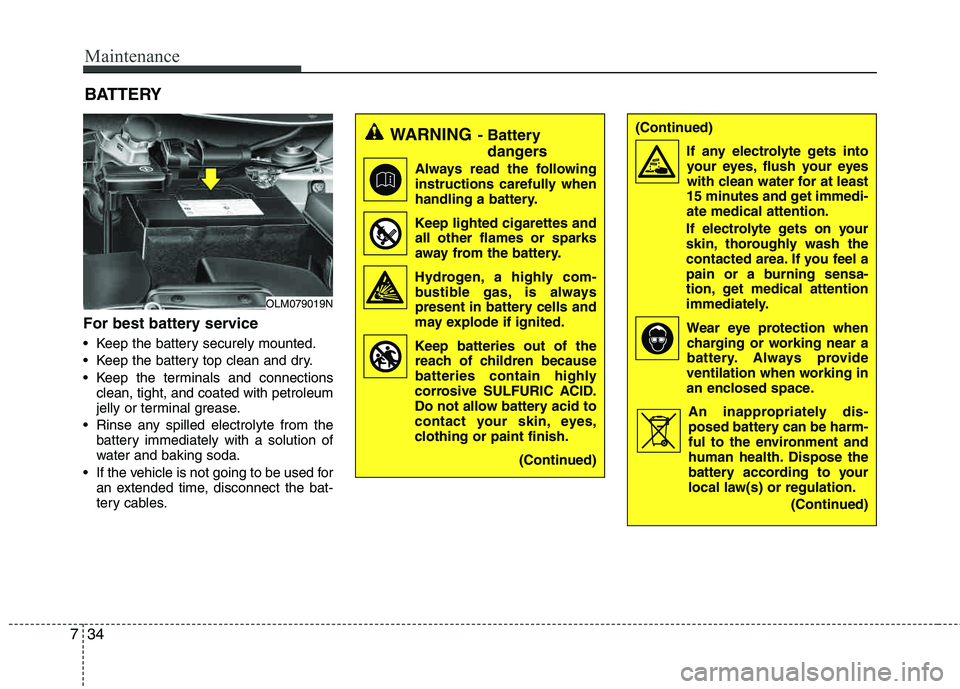
For best battery service
Keep the battery securely mounted.
Keep the battery top clean and dry.
Keep the terminals and connectionsclean, tight, and coated with petroleum
jelly or terminal grease.
Rinse any spilled electrolyte from the battery immediately with a solution of
water and baking soda.
If the vehicle is not going to be used for an extended time, disconnect the bat-
tery cables.
BATTERY
OLM079019N
WARNING- Battery
dangers
Always read the following
instructions carefully when
handling a battery.
Keep lighted cigarettes and all other flames or sparks
away from the battery.
Hydrogen, a highly com- bustible gas, is always
present in battery cells and
may explode if ignited.
Keep batteries out of the reach of children because
batteries contain highly
corrosive SULFURIC ACID.
Do not allow battery acid to
contact your skin, eyes,
clothing or paint finish.
(Continued)
Page 353 of 397

753
Maintenance
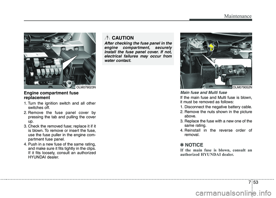
Engine compartment fuse replacement
1. Turn the ignition switch and all otherswitches off.
2. Remove the fuse panel cover by pressing the tab and pulling the cover
up.
3. Check the removed fuse; replace it if it is blown. To remove or insert the fuse,use the fuse puller in the engine com-
partment fuse panel.
4. Push in a new fuse of the same rating, and make sure it fits tightly in the clips.
If it fits loosely, consult an authorized
HYUNDAI dealer.
Main fuse and Multi fuse
If the main fuse and Multi fuse is blown,
it must be removed as follows:
1. Disconnect the negative battery cable.
2. Remove the nuts shown in the picture
above.
3. Replace the fuse with a new one of the same rating.
4. Reinstall in the reverse order of removal.
✽✽ NOTICE
If the main fuse is blown, consult an
authorized HYUNDAI dealer.
CAUTION
After checking the fuse panel in the engine compartment, securelyinstall the fuse panel cover. If not,
electrical failures may occur fromwater contact.
OLM079052NOLM079023N
Page 356 of 397
Maintenance
56
7
Description Fuse rating Protected component
B/UP LP 10A B/UP LP Relay
DR LOCK 15A Door Lock Relay, Tail Gate Relay, Door Unlock Relay
MODULE 5 7.5A BCM, PDM
WIPER RR 15A ICM Relay Box (Rear Wiper Relay), Rear Wiper Motor, Multifunction Switch (Wiper)
SUNROOF 15A Sunroof Motor
IGN 1 20A E/R Fuse & Relay Box(ECU 2 7.5A, ABS 7.5A, TCU 2 7.5A)
A/CON 7.5A A/C Control Module
S/HEATER RR 15A -
P/WDW RH 25A Power Window Main Switch, Passenger Power Window Switch, Rear Power Window Switch RH
MODULE 3 10A -
P/SEAT (DRV) 20A Driver Seat Manual Switch
PDM 15A PDM
P/WDW LH 25A Power Window Main Switch, Rear Power Window Switch LH
AMP 25A AMP
HTD MIRR 7.5A Rear Defogger Switch, Rear Defogger (+), Driver/Passenger Power Outside Mirror
SAFETY POWER WINDOW 20A Driver Safety Power Window Module
TPMS 7.5A ATM Shift Lever, AWD ECM, Tire Pressure Monitoring Module
HAZARD 15A ICM Relay Box(Flasher Sound Relay), BCM
Page 357 of 397

757
Maintenance
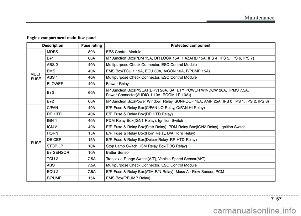
Engine compartment main fuse panel
Description Fuse ratingProtected component
MULTI FUSE MDPS 80A EPS Control Module
B+1 60A I/P Junction Box(PDM 15A, DR LOCK 15A, HAZARD 15A, IPS 4, IPS 5, IPS 6, IPS 7)
ABS 2 40A Multipurpose Check Connector, ESC Control Module
EMS 40A EMS Box(TCU 1 15A, ECU 30A, A/CON 10A, F/PUMP 15A)
ABS 1 40A Multipurpose Check Connector, ESC Control Module
BLOWER 40A Blower Relay
B+3 60A
I/P Junction Box(P/SEAT(DRV) 20A, SAFETY POWER WINDOW 20A, TPMS 7.5A,
Power Connector(AUDIO 1 10A, ROOM LP 10A))
B+2 60A I/P Junction Box(Power Window Relay, SUNROOF 15A, AMP 25A, IPS 0, IPS 1, IPS 2, IPS 3)
FUSE C/FAN 40A E/R Fuse & Relay Box(C/FAN LO Relay, C/FAN HI Relay)
RR HTD 40A E/R Fuse & Relay Box(RR HTD Relay)
IGN 1 40A PDM Relay Box(IGN1 Relay), Ignition Switch
IGN 2 40A E/R Fuse & Relay Box(Statr Relay), PDM Relay Box(IGN2 Relay), Ignition Switch
HORN 15A E/R Fuse & Relay Box(Horn Relay, B/A Horn Relay)
DEICER 15A E/R Fuse & Relay Box(Deicer Relay, RR HTD Relay)
STOP LP 10A Stop Lamp Switch, ICM Relay Box(DBC Relay)
B+ SENSOR 10A Batter Sensor
TCU 2 7.5A Transaxle Range Switch(A/T), Vehicle Speed Sensor(M/T)
ABS 7.5A Multipurpose Check Connector, ESC Control Module
ECU 2 7.5A E/R Fuse & Relay Box(ATM P/N Relay), Mass Air Flow Sensor, PCM
F/PUMP 15A EMS Box(F/PUMP Relay)
Page 358 of 397
Maintenance
58
7
Description Fuse rating Protected component
FUSE SENSOR 4 15A
E/R Fuse & Relay Box(C/FAN HI, LO Relay), EMS Box(F/PUMP Relay),
Oxygen Sensor (UP, DOWN), PCM
SENSOR 3 10A EMS Box(A/CON Relay), Injector(#1, #2, #3, #4)
SENSOR 2 10A -
TCU 1 15A PCM
A/CON 10A EMS Box(A/CON Relay)
SENSOR 1 10A Crankshaft Position Sensor, Camshaft Position Sensor #1/2, Oil Control Valve #1/2,
Canister Purge Control Solenoid Valve, Variable Intake Manifold Valve, Canister Close Valve
ECU 1 20A Ignition Colil (#1, #2, #3, #4), Condenser
ECU 30A EMS Box(Engine Control Relay)
Page 364 of 397
Maintenance
64
7
High mounted stop light replacement
1. Open the tailgate.
2. Gently remove the center cover of the
rear tailgate trim.
3. Disconnect the electrical connector. 4. Loosen the retaining nuts and
remove
the spoiler.
5. Remove the high mounted stop light assembly (A) after loosening the nuts
and washer nozzle (B).
6. Reinstall a new light assembly in the reverse order of removal.
License plate light bulb replace- ment
1. Remove the lens by pressing the tabs.
2. Remove the socket from the lens.
3. Remove the bulb by pulling it straight out.
4. Install a new bulb in the socket and install the socket to the lens.
5. Reinstall the lens securely.
OLM071061L
(A)
(B)
OLM071060L
OLM079039
OLM079055