2013 FORD SUPER DUTY warning light
[x] Cancel search: warning lightPage 209 of 563

For proper operation, make sure
that each hub is fully engaged and
that both hub locks are set to the
same position (both set to LOCK or
both set to AUTO). To engage
LOCK, turn the hub locks
completely clockwise; to engage
AUTO, turn the hub locks
completely counterclockwise.
The ESOF 4WD system:
•provides 4x4 High engagement and disengagement while the vehicle is
moving.
•is operated by a rotary control located on the instrument panel that
allows you select 4x2, 4x4 High or 4x4 Low operation.
•uses auto-manual hub locks that can be engaged and disengaged
automatically based on the 4x4 mode selected.
•will increase fuel economy when used in the recommended AUTO lock
mode.
4WD Indicator Lights
The indicator lights illuminate in the message center in the
reconfigurable telltale (RTT) location under the following conditions.
Refer toWarning Lamps and Indicatorsin theInstrument Cluster
chapter.
Note:When a 4X4 system fault is present, the system will typically
remain in whichever 4X4 mode was selected prior to the fault condition
occurring. It will not default to 4X2 in all circumstances. When this
warning is displayed, have your vehicle serviced by an authorized dealer.
4X2- Momentarily illuminates when 2H is selected.
4X4 HIGH- Continuously illuminates when 4H is selected.
208Four-Wheel Drive (If Equipped)
2013 F-250/350/450/550(f23)
Owners Guide gf, 1st Printing
USA(fus)
Page 221 of 563
GENERAL INFORMATION
Note:Occasional brake noise is normal. If a metal-to-metal, continuous
grinding or continuous squeal sound is present, the brake linings may be
worn-out and should be inspected by an authorized dealer. If your
vehicle has continuous vibration or shudder in the steering wheel while
braking, it should be inspected by an authorized dealer.
Note:Brake dust may accumulate on the wheels, even under normal
driving conditions. Some dust is inevitable as the brakes wear and does
not contribute to brake noise. See theVehicle Carechapter for wheel
cleaning instructions.
See theInstrument Clusterchapter for information on the
brake system warning light.
Wet brakes result in reduced braking efficiency. Gently press the brake
pedal a few times when driving from a car wash or standing water to dry
the brakes.
Brake Over Accelerator
If the accelerator pedal becomes stuck or entrapped, apply steady and
firm pressure to the brake pedal to slow your vehicle and reduce engine
power. If you experience this condition, apply the brakes and bring your
vehicle to a safe stop. Turn the engine off, shift to positionPand apply
the parking brake, then inspect the accelerator pedal for any
interferences. If none are found and the condition persists, have your
vehicle towed to the nearest authorized dealer.
Brake Assist
Brake assist detects when you brake heavily by measuring the rate at
which you press the brake pedal. It provides maximum braking efficiency
as long as you press the pedal. Brake assist can reduce stopping
distances in critical situations.
Anti-Lock Brake System
This system helps you maintain steering control during emergency stops
by keeping the brakes from locking.
The anti-lock brake system lamp momentarily illuminates when
the ignition is turned on. If the light does not illuminate during
start-up, remains on or flashes, the anti-lock brake system may
be disabled and may need to be serviced.
220Brakes
2013 F-250/350/450/550(f23)
Owners Guide gf, 1st Printing
USA(fus)
Page 224 of 563
System indicator lights and messages
WARNING:If a failure has been detected within the Traction
Control System, the stability control light will illuminate steadily.
Verify that the Traction Control System was not manually disabled
using the stability control button. If the stability control light still
illuminates steadily, have the system serviced by an authorized dealer
immediately. Operating your vehicle with Traction Control disabled
could lead to an increased risk of loss of vehicle control, vehicle
rollover, personal injury and death.
The stability control light temporarily illuminates on engine
start-up and flashes when a driving condition activates the
stability system.
The stability control off light temporarily illuminates on engine
start-up and stays on when the traction control system is
turned off or if a problem occurs in the stability system.
Traction Control223
2013 F-250/350/450/550(f23)
Owners Guide gf, 1st Printing
USA(fus)
Page 228 of 563
Hill descent control (if equipped)
Hill descent control allows the driver to set and maintain vehicle speed
while descending steep grades in various surface conditions.
WARNING:Hill descent control cannot control descent in all
surface conditions and circumstances, such as ice or extremely
steep grades. Hill descent control is a driver assist system and cannot
substitute for good judgment by the driver. Failure to do so may result
in loss of vehicle control, crash or serious injury.
Hill descent control can maintain vehicle speeds on downhill grades
between 2 mph (3 km/h) and 12 mph (20 km/h). Above 20 mph
(32 km/h), the system remains armed, but descent speed cannot be set
or maintained.
WARNING:Hill descent control does not provide hill hold at
zero mph (0 km/h). When stopped, the parking brake must be
applied and/or the vehicle must be placed in P (Park) or it may roll
away.
Hill descent control requires a cooling down interval after a period of
sustained use. The amount of time that the feature can remain active
before cooling varies with conditions. The system will provide a warning
in the message center and a chime will sound when the system is about
to disengage for cooling. At this time, manually apply the brakes as
needed to maintain descent speed.
Enabling hill descent control and setting the descent speed
1. Press and release the hill descent button located on
the instrument panel. A light in the cluster will
illuminate and chime will sound when this feature is
activated.
2. To increase descent speed, press the accelerator pedal until the
desired speed is reached. To decrease descent speed, press the brake
pedal until the desired speed is reached.
Terrain Response227
2013 F-250/350/450/550(f23)
Owners Guide gf, 1st Printing
USA(fus)
Page 250 of 563
TOWING A TRAILER
WARNING:Do not exceed the GVWR or the GAWR specified on
the certification label.
WARNING:Towing trailers beyond the maximum recommended
gross trailer weight exceeds the limit of the vehicle and could
result in engine damage, transmission damage, structural damage, loss
of vehicle control, vehicle rollover and personal injury.
Note:For information on electrical items such as fuses or relays, see the
Fuseschapter.
Your vehicle’s load capacity is designated by weight, not by volume, so
you cannot necessarily use all available space when loading a vehicle.
Towing a trailer places an additional load on your vehicle’s engine,
transmission, axle, brakes, tires and suspension. Inspect these
components periodically during, and after, any towing operation.
Load Placement
To help minimize how trailer movement affects the vehicle when driving:
•Load the heaviest items closest to the trailer floor.
•Load the heaviest items so they are centered between the left and
right side trailer tires.
•Load the heaviest items above the trailer axles or just slightly forward
toward the trailer tongue. Do not allow the final trailer tongue weight
to go above or below 10–15% of the loaded trailer weight.
•Select a tow bar with the correct rise or drop. When both the loaded
vehicle and trailer are connected, the trailer frame should be level, or
slightly angled down toward the vehicle, when viewed from the side.
When driving with a trailer or payload, a slight takeoff vibration or
shudder may be present due to the increased payload weight. Additional
information regarding proper trailer loading and setting your vehicle up
for towing is noted underLoad limitin theLoad Carryingchapter and
in theRV & Trailer Towing Guide,available at your authorized dealer.
TRAILER SWAY CONTROL (IF EQUIPPED)
Note:This feature does not prevent trailer sway, but reduces it once it
begins.
Note:This feature cannot stop all trailers from swaying.
Note:In some cases, if vehicle speed is too high, the system may
activate multiple times, gradually reducing vehicle speed.
Towing249
2013 F-250/350/450/550(f23)
Owners Guide gf, 1st Printing
USA(fus)
Page 253 of 563
Hitches
WARNING:ON PICK-UP TRUCKS, the trailer hitch provided on
this vehicle enhances collision protection for the fuel system. DO
NOT REMOVE!
Do not use a hitch that either clamps onto the bumper or attaches to the
axle. You must distribute the load in your trailer so that 10–15% for
conventional towing or 15–25% for fifth-wheel towing of the total weight
of the trailer is on the tongue.
Weight-Distributing Hitches
WARNING:Do not adjust a weight-distributing hitch to any
position where the rear bumper of the vehicle is higher than it
was before attaching the trailer. Doing so will defeat the function of the
weight-distributing hitch, which may cause unpredictable handling, and
could result in serious personal injury.
When hooking-up a trailer using a weight-distributing hitch, always use
the following procedure:
1. Park the loaded vehicle (without the trailer) on a level surface.
2. Measure the height to the top of the vehicle front wheel opening on
the fender, this is H1.
3. Securely attach the loaded trailer to the vehicle without the
weight-distributing bars connected.
4. Measure the height to the top of the vehicle front wheel opening on
the fender a second time, this is H2.
5. Install and adjust the tension in the weight-distributing bars so that
the height of the vehicle’s front wheel opening on the fender is
approximately halfway between H1 and H2.
6. Check that the trailer is level or slightly nose down toward the
vehicle. If not, adjust the ball height accordingly and repeat
Steps 1–6.
7. Lock bar tension adjuster in place.
8. Check that the trailer tongue is securely attached and locked to the
hitch.
9. Install safety chains, lighting, and trailer brake controls as required
by law or the trailer manufacturer.
252Towing
2013 F-250/350/450/550(f23)
Owners Guide gf, 1st Printing
USA(fus)
Page 267 of 563
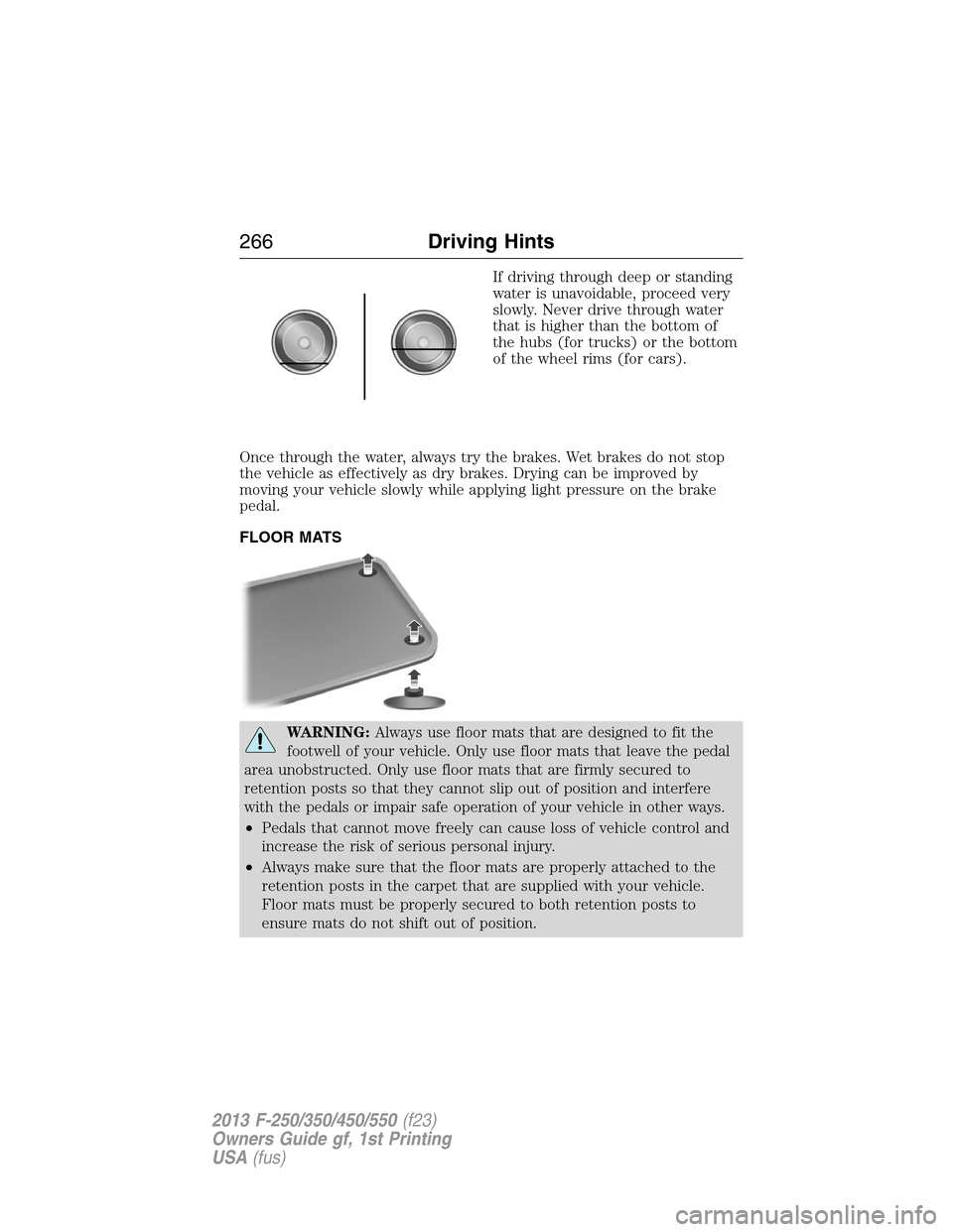
If driving through deep or standing
water is unavoidable, proceed very
slowly. Never drive through water
that is higher than the bottom of
the hubs (for trucks) or the bottom
of the wheel rims (for cars).
Once through the water, always try the brakes. Wet brakes do not stop
the vehicle as effectively as dry brakes. Drying can be improved by
moving your vehicle slowly while applying light pressure on the brake
pedal.
FLOOR MATS
WARNING:Always use floor mats that are designed to fit the
footwell of your vehicle. Only use floor mats that leave the pedal
area unobstructed. Only use floor mats that are firmly secured to
retention posts so that they cannot slip out of position and interfere
with the pedals or impair safe operation of your vehicle in other ways.
•Pedals that cannot move freely can cause loss of vehicle control and
increase the risk of serious personal injury.
•Always make sure that the floor mats are properly attached to the
retention posts in the carpet that are supplied with your vehicle.
Floor mats must be properly secured to both retention posts to
ensure mats do not shift out of position.
266Driving Hints
2013 F-250/350/450/550(f23)
Owners Guide gf, 1st Printing
USA(fus)
Page 268 of 563
WARNING(Continued)
•Never place floor mats or any other covering in the vehicle footwell
that cannot be properly secured to prevent them from moving and
interfering with the pedals or the ability to control the vehicle.
•Never place floor mats or any other covering on top of already
installed floor mats. Floor mats should always rest on top of the
vehicle carpeting surface and not another floor mat or other
covering. Additional floor mats or any other covering will reduce the
pedal clearance and potentially interfere with pedal operation.
•Check attachment of floor mats on a regular basis. Always properly
reinstall and secure floor mats that have been removed for cleaning
or replacement.
•Always make sure that objects cannot fall into the driver footwell
while the vehicle is moving. Objects that are loose can become
trapped under the pedals causing a loss of vehicle control.
•Failure to properly follow floor mat installation or attachment
instructions can potentially cause interference with pedal operation
causing loss of control of vehicle.
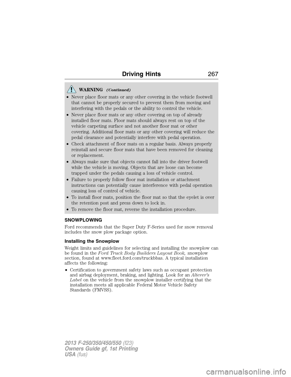
•To install floor mats, position the floor mat so that the eyelet is over
the retention post and press down to lock in.
•To remove the floor mat, reverse the installation procedure.
SNOWPLOWING
Ford recommends that the Super Duty F-Series used for snow removal
includes the snow plow package option.
Installing the Snowplow
Weight limits and guidelines for selecting and installing the snowplow can
be found in theFord Truck Body Builders Layout Book,snowplow
section, found at www.fleet.ford.com/truckbbas. A typical installation
affects the following:
•Certification to government safety laws such as occupant protection
and airbag deployment, braking, and lighting. Look for anAlterer’s
Labelon the vehicle from the snowplow installer certifying that the
installation meets all applicable Federal Motor Vehicle Safety
Standards (FMVSS).
Driving Hints267
2013 F-250/350/450/550(f23)
Owners Guide gf, 1st Printing
USA(fus)