2013 FORD F250 wiring
[x] Cancel search: wiringPage 133 of 577
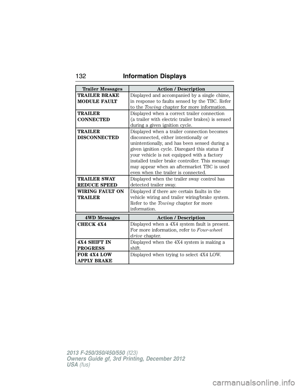
Trailer Messages Action / Description
TRAILER BRAKE
MODULE FAULTDisplayed and accompanied by a single chime,
in response to faults sensed by the TBC. Refer
to theTowingchapter for more information.
TRAILER
CONNECTEDDisplayed when a correct trailer connection
(a trailer with electric trailer brakes) is sensed
during a given ignition cycle.
TRAILER
DISCONNECTEDDisplayed when a trailer connection becomes
disconnected, either intentionally or
unintentionally, and has been sensed during a
given ignition cycle. Disregard this status if
your vehicle is not equipped with a factory
installed trailer brake controller. This message
may appear when an aftermarket TBC is used
even when the trailer is connected.
TRAILER SWAY
REDUCE SPEEDDisplayed when the trailer sway control has
detected trailer sway.
WIRING FAULT ON
TRAILERDisplayed if there are certain faults in the
vehicle wiring and trailer wiring/brake system.
Refer to theTowingchapter for more
information.
4WD Messages Action / Description
CHECK 4X4Displayed when a 4X4 system fault is present.
For more information, refer toFour-wheel
drivechapter.
4X4 SHIFT IN
PROGRESSDisplayed when the 4X4 system is making a
shift.
FOR 4X4 LOW
APPLY BRAKEDisplayed when trying to select 4X4 LOW.
132Information Displays
2013 F-250/350/450/550(f23)
Owners Guide gf, 3rd Printing, December 2012
USA(fus)
Page 256 of 577
Note:Certain states require electric trailer brakes for trailers over a
specified weight. Be sure to check state regulations for this specified
weight. The maximum trailer weights listed may be limited to this
specified weight, as your vehicle’s electrical system may not include
the wiring connector needed to use electric trailer brakes.
Your vehicle may tow a class I, II, III and IV trailer or fifth-wheel trailer
provided the maximum trailer weight is less than or equal to the maximum
trailer weight listed for your engine and rear axle ratio on the following
chart.
To calculate the maximum loaded trailer weight for your vehicle:
1. Start with the gross combined weight rating for your vehicle model
and axle ratio. See the following chart.
2. Subtract all of the following that apply to your vehicle:
•Vehicle curb weight
•Hitch hardware weight, such as a draw bar, ball, locks or weight
distributing
•Driver weight
•Passenger(s) weight
•Payload, cargo and luggage weight
•Aftermarket equipment weight.
3. This equals the maximum loaded trailer weight for this combination.
Note:The trailer tongue load figures into the payload for your vehicle.
Reduce the total payload by the final trailer tongue weight.
Consult an authorized dealer to determine the maximum trailer weight
allowed for your vehicle if you are not sure.
Further trailer and hitch restrictions exist depending on the type of
trailer and hitch listed. This information follows the table listing the
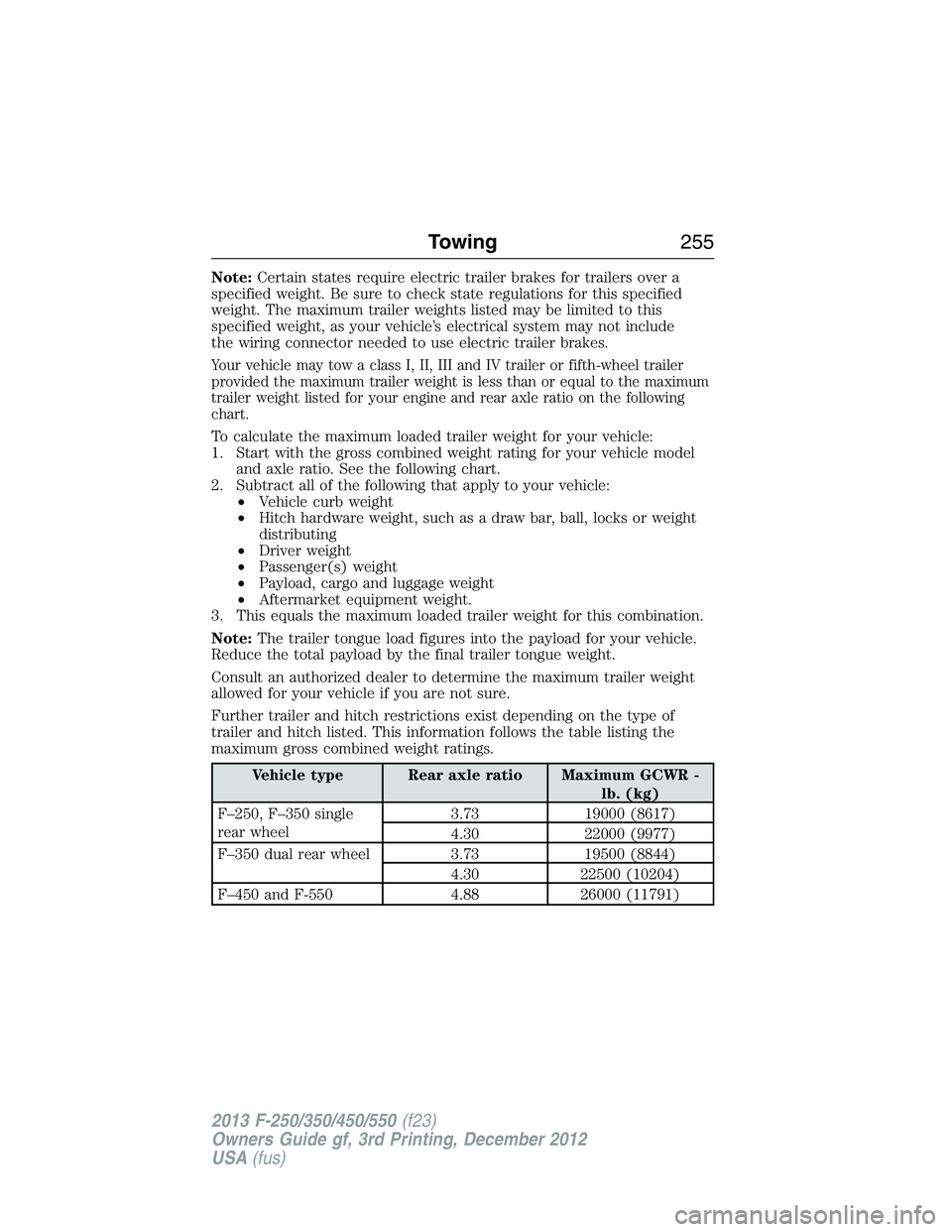
maximum gross combined weight ratings.
Vehicle type Rear axle ratio Maximum GCWR -
lb. (kg)
F–250, F–350 single
rear wheel3.73 19000 (8617)
4.30 22000 (9977)
F–350 dual rear wheel 3.73 19500 (8844)
4.30 22500 (10204)
F–450 and F-550 4.88 26000 (11791)
Towing255
2013 F-250/350/450/550(f23)
Owners Guide gf, 3rd Printing, December 2012
USA(fus)
Page 258 of 577
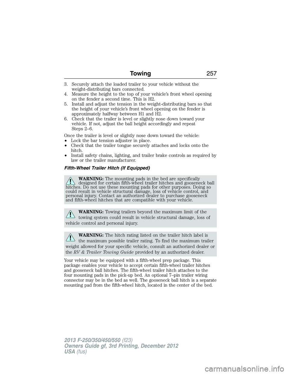
3. Securely attach the loaded trailer to your vehicle without the
weight-distributing bars connected.
4. Measure the height to the top of your vehicle’s front wheel opening
on the fender a second time. This is H2.
5. Install and adjust the tension in the weight-distributing bars so that
the height of your vehicle’s front wheel opening on the fender is
approximately halfway between H1 and H2.
6. Check that the trailer is level or slightly nose down toward your
vehicle. If not, adjust the ball height accordingly and repeat
Steps 2–6.
Once the trailer is level or slightly nose down toward the vehicle:
•Lock the bar tension adjuster in place.
•Check that the trailer tongue securely attaches and locks onto the
hitch.
•Install safety chains, lighting, and trailer brake controls as required by
law or the trailer manufacturer.
Fifth-Wheel Trailer Hitch (If Equipped)
WARNING:The mounting pads in the bed are specifically
designed for certain fifth-wheel trailer hitches and gooseneck ball
hitches. Do not use these mounting pads for other purposes. Doing so
could result in vehicle structural damage, loss of vehicle control, and
personal injury. Contact an authorized dealer to purchase gooseneck
and fifth-wheel hitches that are compatible with your vehicle.
WARNING:Towing trailers beyond the maximum limit of the
towing system could result in vehicle structural damage, loss of
vehicle control and personal injury.
WARNING:The hitch rating listed on the trailer hitch label is
the maximum possible trailer rating. To find the maximum trailer
weight allowed for your specific vehicle, consult an authorized dealer or
theRV & Trailer Towing Guideprovided by an authorized dealer.
Your vehicle may be equipped with a fifth-wheel prep package. This
package enables your vehicle to accept certain fifth-wheel trailer hitches
and gooseneck ball hitches. The fifth-wheel trailer hitch attaches to the
four mounting pads in the pick-up bed. An optional 7–pin trailer wiring
connector may be in the bed as well. The gooseneck ball hitch is a separate
mounting pad from the fifth-wheel hitch, located in the center of the bed.
Towing257
2013 F-250/350/450/550(f23)
Owners Guide gf, 3rd Printing, December 2012
USA(fus)
Page 261 of 577
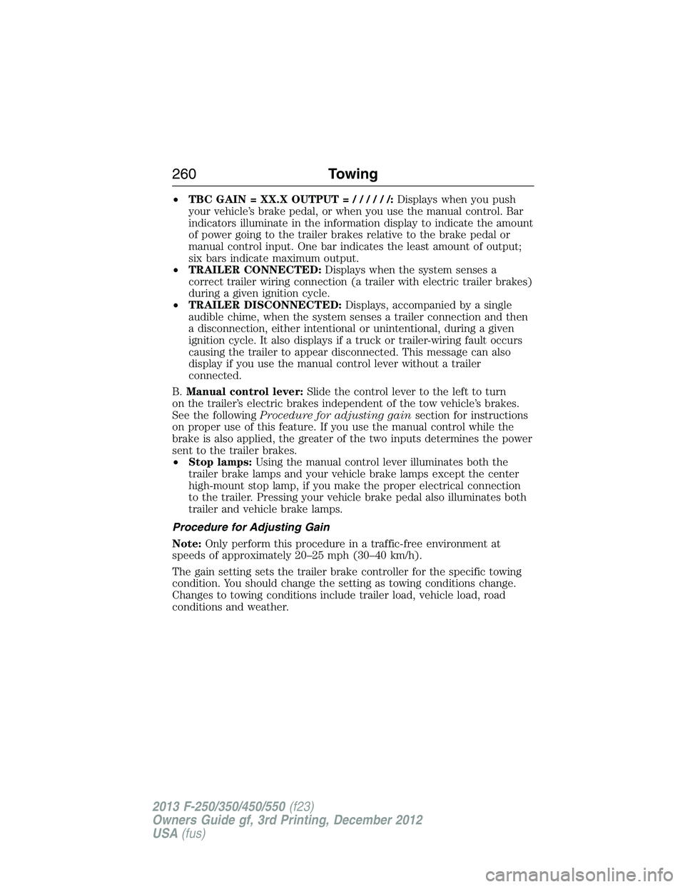
•TBC GAIN = XX.X OUTPUT=//////:Displays when you push
your vehicle’s brake pedal, or when you use the manual control. Bar
indicators illuminate in the information display to indicate the amount
of power going to the trailer brakes relative to the brake pedal or
manual control input. One bar indicates the least amount of output;
six bars indicate maximum output.
•TRAILER CONNECTED:Displays when the system senses a
correct trailer wiring connection (a trailer with electric trailer brakes)
during a given ignition cycle.
•TRAILER DISCONNECTED:Displays, accompanied by a single
audible chime, when the system senses a trailer connection and then
a disconnection, either intentional or unintentional, during a given
ignition cycle. It also displays if a truck or trailer-wiring fault occurs
causing the trailer to appear disconnected. This message can also
display if you use the manual control lever without a trailer
connected.
B.Manual control lever:Slide the control lever to the left to turn
on the trailer’s electric brakes independent of the tow vehicle’s brakes.
See the followingProcedure for adjusting gainsection for instructions
on proper use of this feature. If you use the manual control while the
brake is also applied, the greater of the two inputs determines the power
sent to the trailer brakes.
•Stop lamps:Using the manual control lever illuminates both the
trailer brake lamps and your vehicle brake lamps except the center
high-mount stop lamp, if you make the proper electrical connection
to the trailer. Pressing your vehicle brake pedal also illuminates both
trailer and vehicle brake lamps.
Procedure for Adjusting Gain
Note:Only perform this procedure in a traffic-free environment at
speeds of approximately 20–25 mph (30–40 km/h).
The gain setting sets the trailer brake controller for the specific towing
condition. You should change the setting as towing conditions change.
Changes to towing conditions include trailer load, vehicle load, road
conditions and weather.
260Towing
2013 F-250/350/450/550(f23)
Owners Guide gf, 3rd Printing, December 2012
USA(fus)
Page 262 of 577
The gain should be set to provide the maximum trailer braking assistance
while making sure the trailer wheels do not lock when using the brakes.
Locked trailer wheels may lead to trailer instability.
1. Make sure the trailer brakes are in good working condition,
functioning normally and properly adjusted. See your trailer dealer if
necessary.
2. Hook up the trailer and make the electrical connections according to
the trailer manufacturer’s instructions.
3. When you plug in a trailer with electric or electric-over-hydraulic
brakes,TRAILER CONNECTEDappears in the information display.
4. Use the gain adjustment (+ and -) buttons to increase or decrease
the gain setting to the desired starting point. A gain setting of 6.0 is a
good starting point for heavier loads.
5. In a traffic-free environment, tow the trailer on a dry, level surface at
a speed of 20–25 mph (30–40 km/h) and squeeze the manual control
lever completely.
6. If the trailer wheels lock up, indicated by squealing tires, reduce the
gain setting. If the trailer wheels turn freely, increase the gain setting.
Repeat Steps 5 and 6 until the gain setting is at a point just below
trailer wheel lock-up. If towing a heavier trailer, trailer wheel lock-up
may not be attainable even with the maximum gain setting of 10.
Explanation of Information Display Warning Messages
Note:An authorized dealer can diagnose the trailer brake controller to
determine exactly which trailer fault has occurred. However, your Ford
warranty doesnotcover this diagnosis if the fault is with the trailer.
TRAILER BRAKE MODULE FAULT:Displays in response to faults
sensed by the trailer brake controller, accompanied by a single chime.
If this message appears, contact an authorized dealer as soon as possible
for diagnosis and repair. The controller may still function, but
performance may be degraded.
WIRING FAULT ON TRAILER:Displays when there is a short circuit
on the electric brake output wire. If theWIRING FAULT ON TRAILER
message displays, accompanied by a single chime, with no trailer
connected, the problem is with your vehicle wiring between the trailer
brake controller and the 7–pin connector at the bumper. If the message
only displays with a trailer connected, the problem is with the trailer
wiring. Consult your trailer dealer for assistance. This can be a short to
ground (such as a chaffed wire), short to voltage (such as a pulled pin
on trailer emergency breakaway battery) or the trailer brakes may be
drawing too much current.
Towing261
2013 F-250/350/450/550(f23)
Owners Guide gf, 3rd Printing, December 2012
USA(fus)
Page 264 of 577
Trailer Lamps
WARNING:Never connect any trailer lamp wiring to the
vehicle’s tail lamp wiring; this may damage the electrical system
resulting in a fire. Contact an authorized dealer as soon as possible for
assistance in proper trailer tow wiring installation. Additional electrical
equipment may be required.
Trailer lamps are required on most towed vehicles. Make sure all running
lights, brake lights, turn signals and hazard lights are working.
Using a Step Bumper (If Equipped)
The rear bumper is equipped with an integral hitch and only requires a
ball with a one-inch (25.4 millimeter) shank diameter. The bumper has a
5000-pound (2268 kilogram) trailer weight and a 500-pound (227 kilogram)
tongue weight capacity.
If it is necessary to relocate the hitch ball position, you must install a
frame-mounted trailer hitch.
Before Towing a Trailer
Practice turning, stopping and backing up to get the feel of your
vehicle-trailer combination before starting on a trip. When turning,
make wider turns so the trailer wheels clear curbs and other obstacles.
When Towing a Trailer
•Do not drive faster than 70 mph (113 km/h) during the first 500 miles
(800 kilometers).
•Do not make full-throttle starts.
•Check your hitch, electrical connections and trailer wheel lug nuts
thoroughly after you have traveled 50 miles (80 kilometers).
•When stopped in congested or heavy traffic during hot weather, place
the gearshift in positionPto aid engine and transmission cooling and
to help A/C performance.
•Turn off the speed control with heavy loads or in hilly terrain.
The speed control may turn off automatically when you are towing
on long, steep grades.
•Shift to a lower gear when driving down a long or steep hill. Do not
apply the brakes continuously, as they may overheat and become less
effective.
Towing263
2013 F-250/350/450/550(f23)
Owners Guide gf, 3rd Printing, December 2012
USA(fus)
Page 265 of 577

•If your transmission is equipped with the Tow/Haul feature, use this
when towing. This provides engine braking and helps eliminate
excessive transmission shifting for optimum fuel economy and
transmission cooling.
•If your vehicle is equipped with AdvanceTrac™ with RSC, this system
may turn on during typical cornering maneuvers with a heavily loaded
trailer. This is normal. Turning the corner at a slower speed while
towing may reduce this tendency.
•If you are towing a trailer frequently in hot weather, hilly conditions,
at the gross combined weight rating (or any combination of these
factors), consider refilling your rear axle with synthetic gear lubricant
(if the axle is not already filled with it). See theCapacities and
Specificationschapter for the lubricant specification.
•Allow more distance for stopping with a trailer attached. Anticipate
stops and brake gradually.
•Avoid parking on a grade. However, if you must park on a grade:
1. Turn the steering wheel to point your vehicle tires away from
traffic flow.
2. Set your vehicle parking brake.
3. Place the automatic transmission in positionP.
4. Place wheel chocks in front and back of the trailer wheels.
(Chocks not included with vehicle.)
Your vehicle may be equipped with a temporary or conventional spare
tire. A “temporary” spare tire is different in size (diameter or width),
tread-type (All-Season or All-Terrain) or is from a different manufacturer
than the road tires on your vehicle. Consult information on the tire label
or Safety Compliance label for limitations when using.
Launching or Retrieving a Boat or Personal Watercraft (PWC)
Note:Disconnect the wiring to the trailerbeforebacking the trailer into
the water.
Note:Reconnect the wiring to the trailerafterremoving the trailer from
the water.
When backing down a ramp during boat launching or retrieval:
•Do not allow the static water level to rise above the bottom edge of
the rear bumper.
•Do not allow waves to break higher than 6 inches (15 centimeters)
above the bottom edge of the rear bumper.
264Towing
2013 F-250/350/450/550(f23)
Owners Guide gf, 3rd Printing, December 2012
USA(fus)
Page 331 of 577
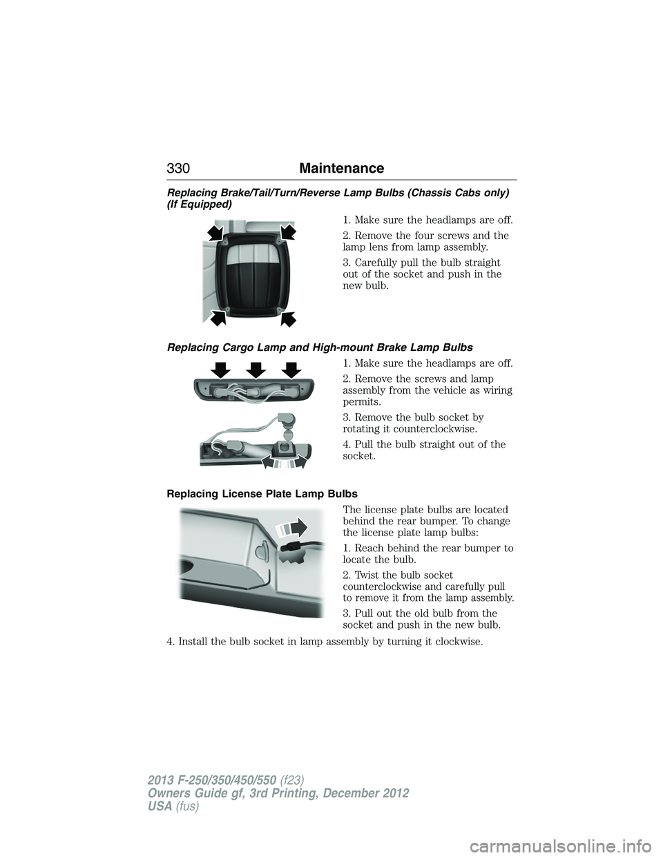
Replacing Brake/Tail/Turn/Reverse Lamp Bulbs (Chassis Cabs only)
(If Equipped)
1. Make sure the headlamps are off.
2. Remove the four screws and the
lamp lens from lamp assembly.
3. Carefully pull the bulb straight
out of the socket and push in the
new bulb.
Replacing Cargo Lamp and High-mount Brake Lamp Bulbs
1. Make sure the headlamps are off.
2. Remove the screws and lamp
assembly from the vehicle as wiring
permits.
3. Remove the bulb socket by
rotating it counterclockwise.
4. Pull the bulb straight out of the
socket.
Replacing License Plate Lamp Bulbs
The license plate bulbs are located
behind the rear bumper. To change
the license plate lamp bulbs:
1. Reach behind the rear bumper to
locate the bulb.
2.
Twist the bulb socket
counterclockwise and carefully pull
to remove it from the lamp assembly.
3. Pull out the old bulb from the
socket and push in the new bulb.
4. Install the bulb socket in lamp assembly by turning it clockwise.
330Maintenance
2013 F-250/350/450/550(f23)
Owners Guide gf, 3rd Printing, December 2012
USA(fus)