2013 FORD F250 service
[x] Cancel search: servicePage 357 of 577

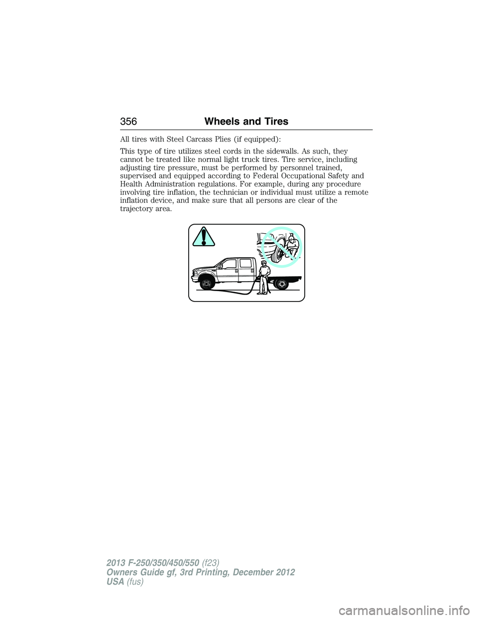
All tires with Steel Carcass Plies (if equipped):
This type of tire utilizes steel cords in the sidewalls. As such, they
cannot be treated like normal light truck tires. Tire service, including
adjusting tire pressure, must be performed by personnel trained,
supervised and equipped according to Federal Occupational Safety and
Health Administration regulations. For example, during any procedure
involving tire inflation, the technician or individual must utilize a remote
inflation device, and make sure that all persons are clear of the
trajectory area.
356Wheels and Tires
2013 F-250/350/450/550(f23)
Owners Guide gf, 3rd Printing, December 2012
USA(fus)
Page 361 of 577

WARNING:To reduce the risk of serious injury, when mounting
replacement tires and wheels, you should not exceed the
maximum pressure indicated on the sidewall of the tire to set the beads
without additional precautions listed below. If the beads do not seat at
the maximum pressure indicated, re-lubricate and try again.
When inflating the tire for mounting pressures up to 20 psi (138 kPa)
greater than the maximum pressure on the tire sidewall, take the
following precautions to protect the person mounting the tire:
1. Make sure that you have the correct tire and wheel size.
2. Lubricate the tire bead and wheel bead seat area again.
3. Stand at a minimum of 12 feet (3.66 meters) away from the tire
wheel assembly.
4. Use both eye and ear protection.
For a mounting pressure more than 20 psi (138 kPa) greater than
the maximum pressure, an authorized dealer or other tire service
professional should do the mounting.
Always inflate steel carcass tires with a remote air fill with the person
inflating standing at a minimum of 12 feet (3.66 meters) away from the
tire wheel assembly.
Your vehicle is equipped with tires designed to provide a safe ride and
handling capability.
Important:Remember to replace the wheel valve stems when the road
tires are replaced on your vehicle.
The two front tires or two rear tires should generally be replaced as a pair.
The tire pressure sensors mounted in the wheels are not designed to be
used in aftermarket wheels.
The use of wheels or tires not recommended by Ford Motor Company
may affect the operation of your tire pressure monitoring system
(if equipped).
If the tire pressure monitoring system indicator is flashing, the system is
malfunctioning. Your replacement tire might be incompatible with your
tire pressure monitoring system, or some component of the system may
be damaged(if equipped).
Safety Practices
WARNING:If your vehicle is stuck in snow, mud, or sand, do not
rapidly spin the tires. Spinning the tires can tear the tire and cause
an explosion. A tire can explode in as little as three to five seconds.
360Wheels and Tires
2013 F-250/350/450/550(f23)
Owners Guide gf, 3rd Printing, December 2012
USA(fus)
Page 367 of 577

Changing Tires with a Tire Pressure Monitoring System
Note:
Each road tire is equipped
with a tire pressure sensor located
inside the tire and wheel assembly
cavity. The pressure sensor is
attached to the valve stem.
The pressure sensor is covered
by the tire and is not visible unless
the tire is removed. Take care when
changing the tire to avoid damaging
the sensor.
You should always have your tires serviced by an authorized dealer.
Check the tire pressure periodically (at least monthly) using an accurate
tire gauge. SeeInflating Your Tiresin this chapter.
Understanding Your Tire Pressure Monitoring System
The tire pressure monitoring system measures pressure in your four road
tires and sends the tire pressure readings to your vehicle. The low tire
pressure warning light will turn on if the tire pressure is significantly low.
Once the light is illuminated, your tires are under-inflated and need to be
inflated to the manufacturer’s recommended tire pressure. Even if the
light turns on and a short time later turns off, your tire pressure still
needs to be checked.
When your temporary spare tire is installed
When one of your road tires needs to be replaced with the temporary
spare, the tire pressure monitoring system will continue to identify an
issue to remind you that the damaged road wheel or tire needs to be
repaired and put back on your vehicle.
To restore the full function of the tire pressure monitoring system, have
the damaged road wheel or tire repaired and remounted on your vehicle.
For additional information, seeChanging Tires with a Tire Pressure
Monitoring Systemin this section.
366Wheels and Tires
2013 F-250/350/450/550(f23)
Owners Guide gf, 3rd Printing, December 2012
USA(fus)
Page 371 of 577

Performing the System Reset Procedure
Read the entire procedure before attempting.
1. Drive the vehicle above 20 mph (32 km/h) for at least two minutes
and then park in a safe location where you can easily get to all four tires
and have access to an air pump.
2. Place the ignition in the off position and keep the key in the ignition.
3. Cycle the ignition to the on position with the engine off.
4. Turn the hazard flashers on then off three times. This must be
accomplished within 10 seconds.
If the reset mode has been entered successfully, the horn will sound
once, the system indicator will flash and a message is shown in the
information display (if equipped). If this does not occur, please try again
starting at Step 2.
If after repeated attempts to enter the reset mode, the horn does not
sound, the system indicator does not flash and no message is shown in the
information display (if equipped), seek service from your authorized dealer.
5.Note:Train the tire pressure monitoring system sensors in the tires
using the following system reset sequence starting with the left front tire
in the following clockwise order:
•Left front (Driver’s side front tire)
•Right front (Passenger’s side front tire)
•Right rear (Passenger’s side rear tire)
•Left rear (Driver’s side rear tire)
6. Remove the valve cap from the valve stem on the left front tire;
decrease the air pressure until the horn sounds.
Note:The single horn chirp confirms that the sensor identification code
has been learned by the module for this position. If a double horn is
heard, the reset procedure was unsuccessful, and must be repeated.
7. Remove the valve cap from the valve stem on the right front tire;
decrease the air pressure until the horn sounds.
8. Remove the valve cap from the valve stem on the right rear tire;
decrease the air pressure until the horn sounds.
9. Remove the valve cap from the valve stem on the left rear tire;
decrease the air pressure until the horn sounds.
Training is complete after the horn sounds for the last tire trained
(driver’s side rear tire), the system indicator stops flashing, and a
message is shown in the information display (if equipped).
370Wheels and Tires
2013 F-250/350/450/550(f23)
Owners Guide gf, 3rd Printing, December 2012
USA(fus)
Page 372 of 577

10. Turn the ignition off. If two short horn beeps are heard, the reset
procedure was unsuccessful and must be repeated.
If after repeating the procedure and two short beeps are heard when the
ignition is turned to off, seek assistance from your authorized dealer.
11. Set all four tires to the recommended air pressure as indicated on
the Safety Compliance Certification Label (affixed to either the door
hinge pillar, door-latch post, or the door edge that meets the door-latch
post, next to the driver’s seating position) or Tire Label located on the
B-Pillar or the edge of the driver’s door. SeeLoad Carryingfor more
information.
CHANGING A ROAD WHEEL
WARNING:The use of tire sealants may damage your tire
pressure monitoring system and should not be used. However, if
you must use a sealant, the tire pressure monitoring system sensor and
valve stem on the wheel must be replaced by an authorized Ford dealer.
WARNING:SeeTire Pressure Monitoring Systemin this
chapter for important information. If the tire pressure monitor
sensor becomes damaged, it will no longer function.
Note:
If your vehicle is equipped with the tire pressure monitoring system,
the indicator light will illuminate when the spare tire is in use. To restore
the full function of the monitoring system, all road wheels equipped with
tire pressure monitoring sensors must be mounted on the vehicle.
If you get a flat tire while driving, do not apply the brake heavily.
Instead, gradually decrease your speed. Hold the steering wheel firmly
and slowly move to a safe place on the side of the road.
If your vehicle is equipped with the tire pressure monitoring system,
have a flat serviced by an authorized dealer in order to prevent damage
to the system sensors. SeeTire Pressure Monitoring Systemin this
chapter. Replace the spare tire with a road tire as soon as possible.
During repairing or replacing of the flat tire, have the authorized dealer
inspect the system sensor for damage.
Wheels and Tires371
2013 F-250/350/450/550(f23)
Owners Guide gf, 3rd Printing, December 2012
USA(fus)
Page 374 of 577

3.Full-size dissimilar spare without label on wheel
When driving with the full-size dissimilar spare tire and wheel assembly,
do not:
•exceed 70 mph (113 km/h).
•use more than one dissimilar spare tire and wheel at a time.
•use commercial car washing equipment.
•use snow chains on the end of the vehicle with the dissimilar spare
tire and wheel.
The usage of a full-size dissimilar spare tire and wheel assembly can lead
to impairment of the following:
•Handling, stability and braking performance
•Comfort and noise
•Ground clearance and parking at curbs
•Winter weather driving capability
•Wet weather driving capability
•All-wheel driving capability (if applicable)
•Load leveling adjustment (if applicable)
When driving with the full-size dissimilar spare tire and wheel assembly,
additional caution should be given to:
•towing a trailer.
•driving vehicles equipped with a camper body.
•driving vehicles with a load on the cargo rack.
Drive cautiously when using a full-size dissimilar spare tire and wheel,
and seek service as soon as possible.
Location of the Spare Tire and Tools
If your vehicle is equipped with a spare tire, jack and associated tools,
refer to the following table for their locations:
Tool Location
Spare tire (pick-up trucks only) Under the vehicle, just forward of
the rear bumper
Jack Regular cab and Crew Cab:
Fastened to floor pan behind
rearmost seat on passenger side
SuperCab: Under rear bench seat
on passenger side
Wheels and Tires373
2013 F-250/350/450/550(f23)
Owners Guide gf, 3rd Printing, December 2012
USA(fus)
Page 387 of 577

Stowing the flat/spare tire
Note:Failure to follow spare tire stowage instructions may result in
failure of cable or loss of spare tire.
Note:
If you are stowing a tire that requires reattaching it to the vehicle
with a tether, perform these steps first, then proceed with the steps
following.
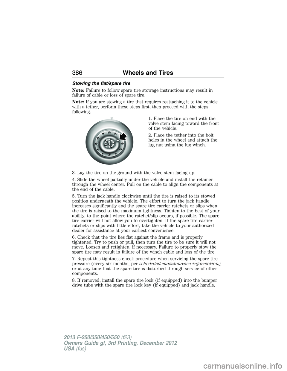
1. Place the tire on end with the
valve stem facing toward the front
of the vehicle.
2. Place the tether into the bolt
holes in the wheel and attach the
lug nut using the lug winch.
3. Lay the tire on the ground with the valve stem facing up.
4. Slide the wheel partially under the vehicle and install the retainer
through the wheel center. Pull on the cable to align the components at
the end of the cable.
5. Turn the jack handle clockwise until the tire is raised to its stowed
position underneath the vehicle. The effort to turn the jack handle
increases significantly and the spare tire carrier ratchets or slips when
the tire is raised to the maximum tightness. Tighten to the best of your
ability, to the point where the ratchet/slip occurs, if possible. The spare
tire carrier will not allow you to overtighten. If the spare tire carrier
ratchets or slips with little effort, take the vehicle to your authorized
dealer for assistance at your earliest convenience.
6. Check that the tire lies flat against the frame and is properly
tightened. Try to push or pull, then turn the tire to be sure it will not
move. Loosen and retighten, if necessary. Failure to properly stow the
spare tire may result in failure of the winch cable and loss of the tire.
7. Repeat this tightness check procedure when servicing the spare tire
pressure (every six months, perscheduled maintenance information),
or at any time that the spare tire is disturbed through service of other
components.
8. If removed, install the spare tire lock (if equipped) into the bumper
drive tube with the spare tire lock key (if equipped) and jack handle.
386Wheels and Tires
2013 F-250/350/450/550(f23)
Owners Guide gf, 3rd Printing, December 2012
USA(fus)
Page 394 of 577

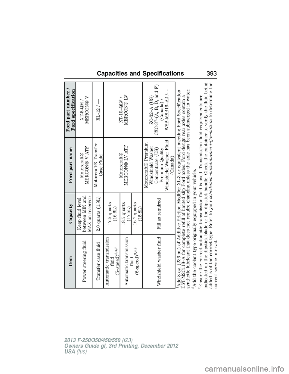
Item Capacity Ford part nameFord part number /
Ford specification
Power steering fluidKeep fluid level
between MIN and
MAX on reservoirMotorcraft®
MERCON® V ATFXT-5-QM /
MERCON® V
Transfer case fluid 2.0 quarts (1.9L)Motorcraft® Transfer
Case FluidXL-12 / —
Automatic transmission
fluid
(5–speed)
3,4,7
17.5 quarts
(16.6L)
Motorcraft®
MERCON® LV ATFXT-10–QLV /
MERCON® LV
Automatic transmission
fluid
(6-speed)
3,4,8
18.5 quarts
(17.5L)
16.7 quarts
(15.8L)
Windshield washer fluid Fill as requiredMotorcraft® Premium
Windshield Washer
Concentrate (US)
Premium Quality
Windshield Washer Fluid
(Canada)ZC-32–A (US)
CXC-37-(A, B, D, and F)
(Canada) /
WSB-M8B16–A2 /- -
1Add 8 oz. (236 ml) of Additive Friction Modifier XL-3 or equivalent meeting Ford Specification
EST-M2C118–A for complete refill of limited slip Ford axles. Ford design rear axles contain a
synthetic lubricant that does not require changing unless the axle has been submerged in water.2Add the coolant type originally equipped in your vehicle.3Ensure the correct automatic transmission fluid is used. Transmission fluid requirements are
indicated on the dipstick blade or the dipstick handle. Check the container to verify the fluid being
added is of the correct type. Refer to yourscheduled maintenance informationto determine the
correct service interval.
Capacities and Specifications393
2013 F-250/350/450/550(f23)
Owners Guide gf, 3rd Printing, December 2012
USA(fus)