2013 FORD F250 display
[x] Cancel search: displayPage 216 of 577

Activating the Electronic Locking Differential (ELD)
Note:The ELD may have difficulty disengaging either by operator
command or automatically if the driveline is under torque. If driving
conditions allow, releasing the accelerator pedal or turning the steering
wheel in the opposite direction may assist in disengagement.
Note:The ELD is designed for off-road use only and is not intended for
use on dry pavement.
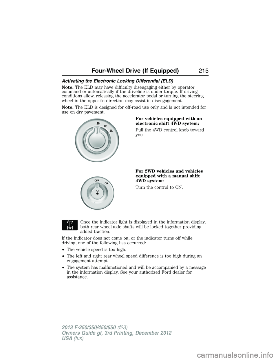
For vehicles equipped with an
electronic shift 4WD system:
Pull the 4WD control knob toward
you.
For 2WD vehicles and vehicles
equipped with a manual shift
4WD system:
Turn the control to ON.
Once the indicator light is displayed in the information display,
both rear wheel axle shafts will be locked together providing
added traction.
If the indicator does not come on, or the indicator turns off while
driving, one of the following has occurred:
•The vehicle speed is too high.
•The left and right rear wheel speed difference is too high during an
engagement attempt.
•The system has malfunctioned and will be accompanied by a message
in the information display. See your authorized Ford dealer for
assistance.
2H
4H
4L
Four-Wheel Drive (If Equipped)215
2013 F-250/350/450/550(f23)
Owners Guide gf, 3rd Printing, December 2012
USA(fus)
Page 232 of 577

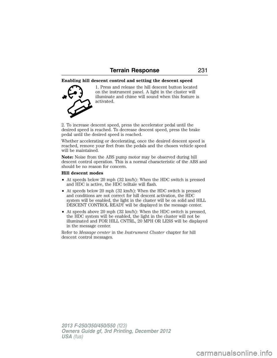
Enabling hill descent control and setting the descent speed
1. Press and release the hill descent button located
on the instrument panel. A light in the cluster will
illuminate and chime will sound when this feature is
activated.
2. To increase descent speed, press the accelerator pedal until the
desired speed is reached. To decrease descent speed, press the brake
pedal until the desired speed is reached.
Whether accelerating or decelerating, once the desired descent speed is
reached, remove your feet from the pedals and the chosen vehicle speed
will be maintained.
Note:Noise from the ABS pump motor may be observed during hill
descent control operation. This is a normal characteristic of the ABS and
should be no reason for concern.
Hill descent modes
•At speeds below 20 mph (32 km/h): When the HDC switch is pressed
and HDC is active, the HDC telltale will flash.
•
At speeds below 20 mph (32 km/h): When the HDC switch is pressed
and conditions are not correct for hill descent activation, the HDC
system will be enabled, the light in the cluster will be on solid and HILL
DESCENT CONTROL READY will be displayed in the message center.
•At speeds above 20 mph (32 km/h): When the HDC switch is pressed,
the HDC system will be enabled, the light in the cluster will not be
illuminated and FOR HILL CNTRL, 20 MPH OR LESS will be displayed
in the message center.
Refer toMessage centerin theInstrument Clusterchapter for hill
descent control messages.
Terrain Response231
2013 F-250/350/450/550(f23)
Owners Guide gf, 3rd Printing, December 2012
USA(fus)
Page 233 of 577

SENSING SYSTEM (IF EQUIPPED)
WARNING:To help avoid personal injury, please read and
understand the limitations of the system as contained in this
section. Sensing is only an aid for some (generally large and fixed)
objects when moving in reverse on a flat surface at parking speeds.
Traffic control systems, inclement weather, air brakes, and external
motors and fans may also affect the function of the sensing system;
this may include reduced performance or a false activation.
WARNING:To help avoid personal injury, always use caution
when in R (Reverse) and when using the sensing system.
WARNING:This system is not designed to prevent contact with
small or moving objects. The system is designed to provide a
warning to assist the driver in detecting large stationary objects to
avoid damaging the vehicle. The system may not detect smaller objects,
particularly those close to the ground.
WARNING:Certain add-on devices such as large trailer hitches,
bike or surfboard racks and any device that may block the normal
detection zone of the system, may create false beeps.
Note:Keep the sensors (located on the bumper/fascia) free from snow,
ice and large accumulations of dirt. If the sensors are covered, the
system’s accuracy can be affected. Do not clean the sensors with sharp
objects.
Note:If your vehicle sustains damage to the bumper/fascia, leaving it
misaligned or bent, the sensing zone may be altered causing inaccurate
measurement of obstacles or false alarms.
Note:If your vehicle is equipped with MyKey®, it is possible to prevent
turning the sensing system off. Refer to theMyKey®chapter.
Note:If your vehicle is equipped with a fully integrated electronic
trailer brake controller (TBC) and a trailer with electric trailer brakes is
connected to your vehicle, the RSS will be disabled. When the vehicle is
shifted into reverse, the message center display will remain in the Rear
Park Aid Off selection. For more information on the TBC, refer to the
Towingchapter.
232Parking Aids
2013 F-250/350/450/550(f23)
Owners Guide gf, 3rd Printing, December 2012
USA(fus)
Page 235 of 577

REAR VIEW CAMERA SYSTEM (IF EQUIPPED)
WARNING:The rear view camera system is a reverse aid
supplement device that still requires the driver to use it in
conjunction with the interior and exterior mirrors for maximum
coverage.
WARNING:Objects that are close to either corner of the
bumper or under the bumper, might not be seen on the screen
due to the limited coverage of the camera system.
WARNING:Back up as slow as possible since higher speeds
might limit your reaction time to stop the vehicle.
WARNING:Use caution when turning camera features on or off
while in R (Reverse). Make sure the vehicle is not moving.
The rear view camera system provides a video image of the area behind
the vehicle.
During operation, lines appear in the display which represent your
vehicle’s path and proximity to objects behind the vehicle.
The camera is located on the
tailgate.
234Parking Aids
2013 F-250/350/450/550(f23)
Owners Guide gf, 3rd Printing, December 2012
USA(fus)
Page 236 of 577

Using the Rear View Camera System
The rear view camera system displays what is behind your vehicle when
you place the transmission in R (Reverse). The system uses two types of
guides to help you see what is behind your vehicle:
1. Fixed guidelines: Show the actual path the vehicle is moving in while
reversing in a straight line, which can be helpful when backing into a
parking space or aligning the vehicle with another object behind the
vehicle.
2. Centerline: Helps align the center of the vehicle with an object
(i.e. a trailer).
Note:If the image comes on while the transmission is not in R
(Reverse), have the system inspected by your authorized dealer.
Note:When towing, the camera only sees what is being towed behind
the vehicle. This might not provide adequate coverage as it usually
provides in normal operation and some objects might not be seen.
In some vehicles, the guidelines may disappear once the trailer tow
connector is engaged.
Note:The default setting for the camera delay is off. Press the Settings
button found on the navigation screen (if equipped) to set the camera
delay feature to on or off.
Note:The camera may not operate correctly under the following
conditions:
•Nighttime or dark areas if one or both reverse lamps are not
operating.
•The camera’s view is obstructed by mud, water or debris. Clean the
lens with a soft, lint-free cloth and non-abrasive cleaner.
•The rear of the vehicle is hit or damaged, causing the camera to
become misaligned.
Parking Aids235
2013 F-250/350/450/550(f23)
Owners Guide gf, 3rd Printing, December 2012
USA(fus)
Page 237 of 577

Guidelines and the Centerline
Note:Fixed guidelines are only available when the transmission is in R
(Reverse).
Note:The centerline is only available if fixed guidelines are on.
A. Rear bumper
B. Fixed guideline: Red zone
C. Fixed guideline: Yellow zone
D. Fixed guideline: Green zone
E. Centerline
The fixed guidelines fade in and out depending on the steering wheel
position.
Always use caution while reversing. Objects in the red zone are closest
to your vehicle and objects in the green zone are further away. Objects
are getting closer to your vehicle as they move from the green zone to
the yellow or red zones. Use the side view mirrors and rear view mirror
to get better coverage on both sides and rear of the vehicle.
Selectable settings for this feature are FIXED and OFF.
Visual Park Aid Alert
Note:Visual park alert is only available when the transmission is in R
(Reverse).
Note:The reverse sensing system is not effective at speeds above 3 mph
(5 km/h) and may not detect certain angular or moving objects.
The visual park aid alert allows the driver to view the area that is being
detected by the reverse sensing system. The system uses red, yellow
and green highlights which appear on top of the video image when an
object is detected by the reverse sensing system. The alert highlights the
closest object detected. The reverse sensing alert can be disabled and if
visual park aid alert is enabled, highlighted areas are still displayed.
Selectable settings for this feature are ON and OFF.
A
E
D
C
B
236Parking Aids
2013 F-250/350/450/550(f23)
Owners Guide gf, 3rd Printing, December 2012
USA(fus)
Page 238 of 577

Rear Camera Delay
Navigation display
When shifting the transmission out of R (Reverse) and into any gear
other than P (Park), the camera image remains in the display until the
vehicle speed reaches 5 mph (8 km/h). This occurs when the rear
camera delay feature is on, or until a radio button is selected.
Selectable settings for this feature are ON and OFF. The default setting
for the rear camera delay is OFF.
Rearview mirror display
When shifting out of R (Reverse) and into any other gear, the image in
the rearview mirror will remain on for a few seconds before it shuts off
to assist in parking or trailer hookup.
Parking Aids237
2013 F-250/350/450/550(f23)
Owners Guide gf, 3rd Printing, December 2012
USA(fus)
Page 260 of 577

Integrated Trailer Brake Controller (If Equipped)
WARNING:The Ford TBC has been verified to be compatible with
trailers having electric-actuated drum brakes (one to four axles)
and some electric-over-hydraulic (EOH) brakes. It will not activate
hydraulic surge-style trailer brakes. It is the responsibility of the customer
to ensure that the trailer brakes are adjusted appropriately, functioning
normally and all electric connections are properly made. Failure to do so
may result in loss of vehicle control, crash or serious injury.
When used properly, the trailer brake controller assists in smooth
and effective trailer braking by powering the trailer’s electric or
electric-over-hydraulic brakes with a proportional output based on the
towing vehicle’s brake pressure.
Ford has tested the trailer brake controller to be compatible with several
major brands of electric-over-hydraulic trailer brakes. Contact an
authorized dealer for information on which brands you can use.
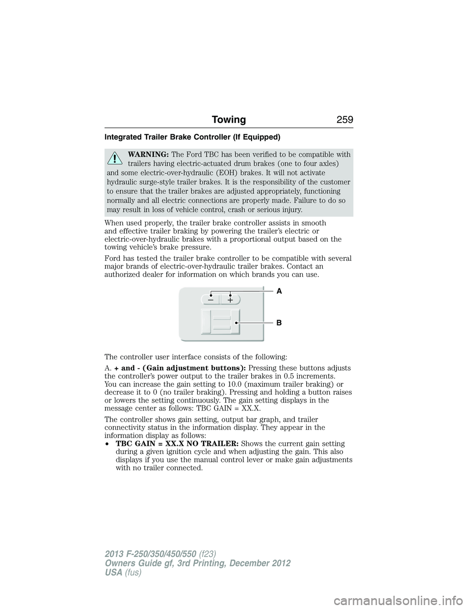
The controller user interface consists of the following:
A.+ and - (Gain adjustment buttons):Pressing these buttons adjusts
the controller’s power output to the trailer brakes in 0.5 increments.
You can increase the gain setting to 10.0 (maximum trailer braking) or
decrease it to 0 (no trailer braking). Pressing and holding a button raises
or lowers the setting continuously. The gain setting displays in the
message center as follows: TBC GAIN = XX.X.
The controller shows gain setting, output bar graph, and trailer
connectivity status in the information display. They appear in the
information display as follows:
•TBC GAIN = XX.X NO TRAILER:Shows the current gain setting
during a given ignition cycle and when adjusting the gain. This also
displays if you use the manual control lever or make gain adjustments
with no trailer connected.
B
A
Towing259
2013 F-250/350/450/550(f23)
Owners Guide gf, 3rd Printing, December 2012
USA(fus)