Page 232 of 577
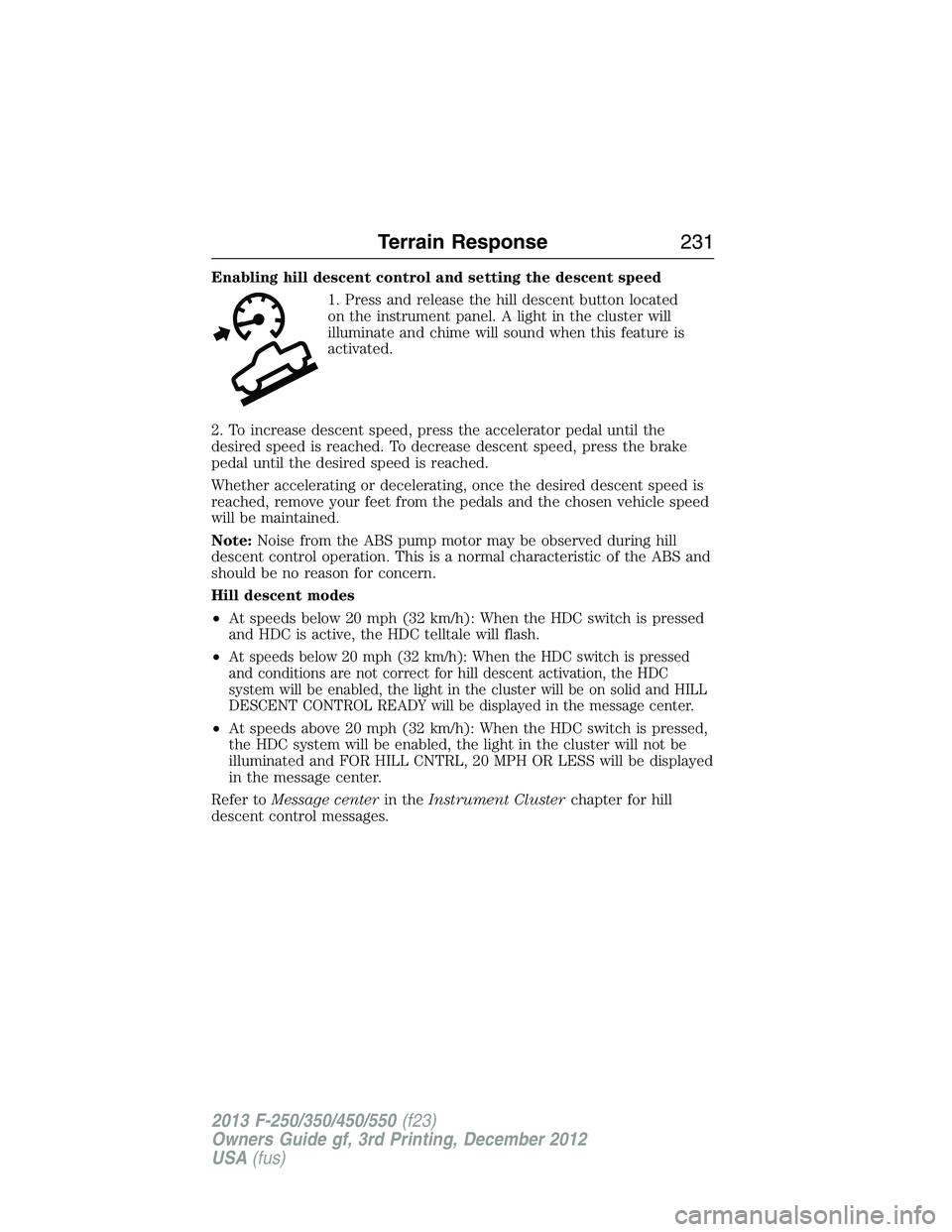
Enabling hill descent control and setting the descent speed
1. Press and release the hill descent button located
on the instrument panel. A light in the cluster will
illuminate and chime will sound when this feature is
activated.
2. To increase descent speed, press the accelerator pedal until the
desired speed is reached. To decrease descent speed, press the brake
pedal until the desired speed is reached.
Whether accelerating or decelerating, once the desired descent speed is
reached, remove your feet from the pedals and the chosen vehicle speed
will be maintained.
Note:Noise from the ABS pump motor may be observed during hill
descent control operation. This is a normal characteristic of the ABS and
should be no reason for concern.
Hill descent modes
•At speeds below 20 mph (32 km/h): When the HDC switch is pressed
and HDC is active, the HDC telltale will flash.
•
At speeds below 20 mph (32 km/h): When the HDC switch is pressed
and conditions are not correct for hill descent activation, the HDC
system will be enabled, the light in the cluster will be on solid and HILL
DESCENT CONTROL READY will be displayed in the message center.
•At speeds above 20 mph (32 km/h): When the HDC switch is pressed,
the HDC system will be enabled, the light in the cluster will not be
illuminated and FOR HILL CNTRL, 20 MPH OR LESS will be displayed
in the message center.
Refer toMessage centerin theInstrument Clusterchapter for hill
descent control messages.
Terrain Response231
2013 F-250/350/450/550(f23)
Owners Guide gf, 3rd Printing, December 2012
USA(fus)
Page 279 of 577
HAZARD FLASHER CONTROL
Note:The hazard warning flashers will operate when the ignition is in
any position or if the key is not in the ignition. If used when the engine
is not running, the battery will lose charge. As a result, there may be
insufficient power to restart your engine.
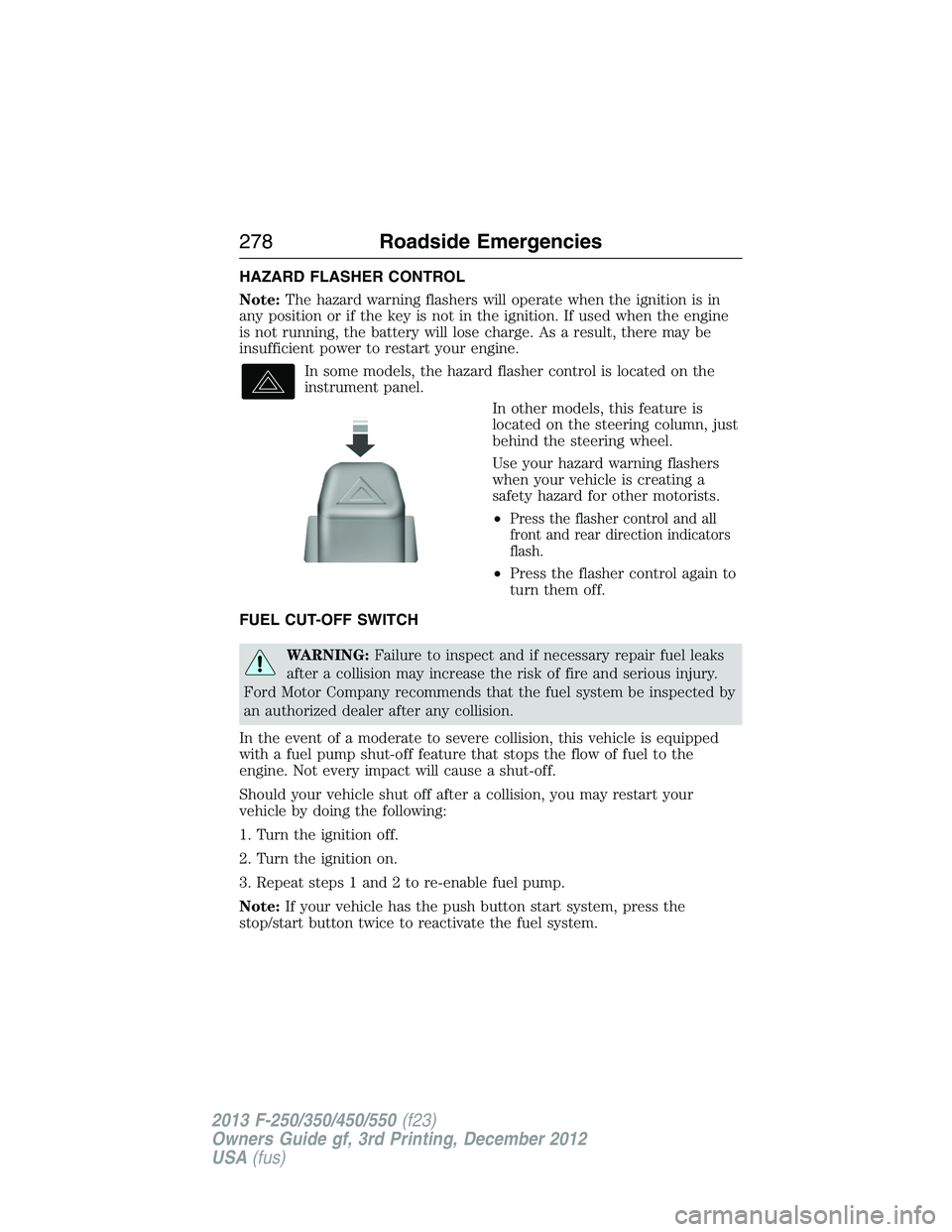
In some models, the hazard flasher control is located on the
instrument panel.
In other models, this feature is
located on the steering column, just
behind the steering wheel.
Use your hazard warning flashers
when your vehicle is creating a
safety hazard for other motorists.
•
Press the flasher control and all
front and rear direction indicators
flash.
•Press the flasher control again to
turn them off.
FUEL CUT-OFF SWITCH
WARNING:Failure to inspect and if necessary repair fuel leaks
after a collision may increase the risk of fire and serious injury.
Ford Motor Company recommends that the fuel system be inspected by
an authorized dealer after any collision.
In the event of a moderate to severe collision, this vehicle is equipped
with a fuel pump shut-off feature that stops the flow of fuel to the
engine. Not every impact will cause a shut-off.
Should your vehicle shut off after a collision, you may restart your
vehicle by doing the following:
1. Turn the ignition off.
2. Turn the ignition on.
3. Repeat steps 1 and 2 to re-enable fuel pump.
Note:If your vehicle has the push button start system, press the
stop/start button twice to reactivate the fuel system.
278Roadside Emergencies
2013 F-250/350/450/550(f23)
Owners Guide gf, 3rd Printing, December 2012
USA(fus)
Page 296 of 577
Fuse or relay
locationFuse amp
ratingProtected circuits
88 20A* Auxiliary power point #6
89 40A* Starter motor
90 25A* Trailer tow battery charge
91 — Not used
92 20A* Auxiliary power point #4
93 20A* Auxiliary power point #3
94 25A* Upfitter #1
95 25A* Upfitter #2
96 50A* Anti-lock brake system pump
97 40A* Inverter
98 — Not used
99 40A* Instrument panel power inverter
100 25A* Trailer tow turn signals
101 Relay Starter
102 Relay Trailer tow battery charge
103 — Not used
104 — Not used
105 — Not used
106 — Not used
107 — Not used
* Cartridge fuses ** Mini fuses
Fuses295
2013 F-250/350/450/550(f23)
Owners Guide gf, 3rd Printing, December 2012
USA(fus)
Page 301 of 577
Fuse or relay
locationFuse amp
ratingProtected circuits
48 30A Circuit
BreakerPower windows switch, Power
rear sliding window switch
49 Relay Delayed accessory
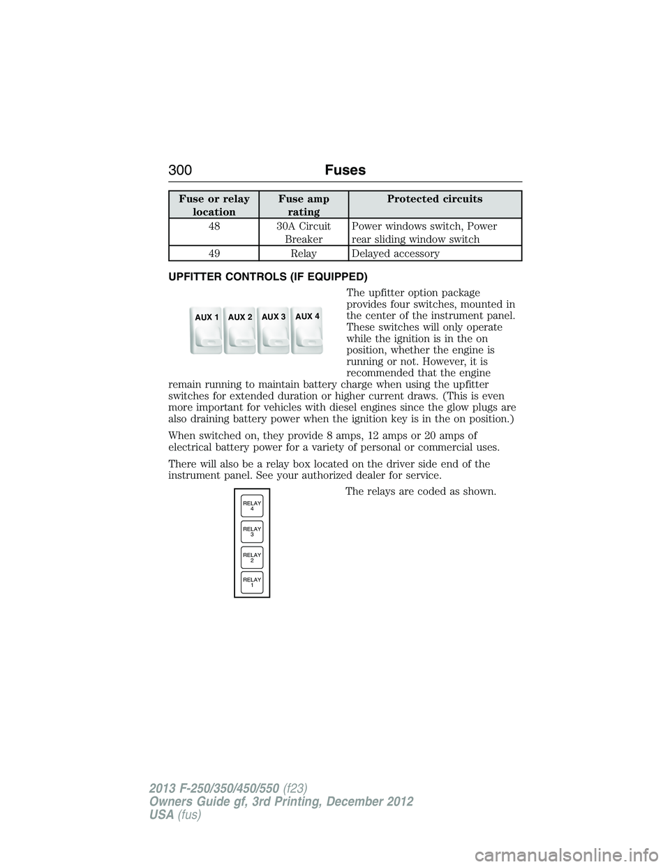
UPFITTER CONTROLS (IF EQUIPPED)
The upfitter option package
provides four switches, mounted in
the center of the instrument panel.
These switches will only operate
while the ignition is in the on
position, whether the engine is
running or not. However, it is
recommended that the engine
remain running to maintain battery charge when using the upfitter
switches for extended duration or higher current draws. (This is even
more important for vehicles with diesel engines since the glow plugs are
also draining battery power when the ignition key is in the on position.)
When switched on, they provide 8 amps, 12 amps or 20 amps of
electrical battery power for a variety of personal or commercial uses.
There will also be a relay box located on the driver side end of the
instrument panel. See your authorized dealer for service.
The relays are coded as shown.
AUX 1
AUX 2
AUX 3
AUX 4
RELAY
1 RELAY
2 RELAY
3 RELAY
4
300Fuses
2013 F-250/350/450/550(f23)
Owners Guide gf, 3rd Printing, December 2012
USA(fus)
Page 302 of 577
There will also be one power lead
for each switch found as a blunt-cut
and sealed wire located below the
instrument panel and to the left of
the steering column.
They are coded as follows:
SwitchCircuit
NumberWire ColorFuse Amp
Rating
AUX 1 CAC05 Yellow 25A
AUX 2 CAC06 Green with
Brown Trace25A
AUX 3 CAC07 Violet with
Green Trace10A
AUX 4 CAC08 Brown 15A
More detailed information about upfitter switches can be found at
https://www.fleet.ford.com/truckbbas/.
Fuses301
2013 F-250/350/450/550(f23)
Owners Guide gf, 3rd Printing, December 2012
USA(fus)
Page 304 of 577
Working with the Engine Off
1. Set the parking brake and shift toP(Park).
2. Turn off the engine and remove the key (if equipped).
3. Block the wheels.
Working with the Engine On
WARNING:To reduce the risk of vehicle damage or personal
burn injuries, do not start your engine with the air cleaner
removed and do not remove it while the engine is running.
1. Set the parking brake and shift to positionP.
2. Block the wheels.
OPENING AND CLOSING THE HOOD
1. Inside the vehicle, pull the hood
release handle located under the
bottom left corner of the instrument
panel.
2. Go to the front of the vehicle to
release the auxiliary latch located
at the top center of the grille.
Slide the handle left to release
the auxiliary latch.
3. Lift the hood until the lift
cylinders hold it open.
BRAKE
HOOD
Maintenance303
2013 F-250/350/450/550(f23)
Owners Guide gf, 3rd Printing, December 2012
USA(fus)
Page 332 of 577
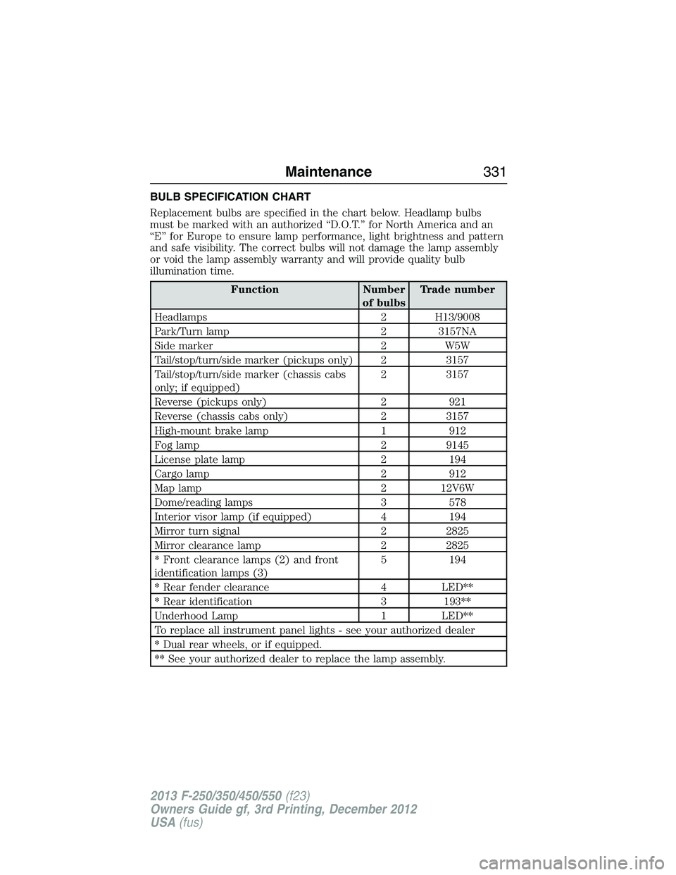
BULB SPECIFICATION CHART
Replacement bulbs are specified in the chart below. Headlamp bulbs
must be marked with an authorized “D.O.T.” for North America and an
“E” for Europe to ensure lamp performance, light brightness and pattern
and safe visibility. The correct bulbs will not damage the lamp assembly
or void the lamp assembly warranty and will provide quality bulb
illumination time.
Function Number
of bulbsTrade number
Headlamps 2 H13/9008
Park/Turn lamp 2 3157NA
Side marker 2 W5W
Tail/stop/turn/side marker (pickups only) 2 3157
Tail/stop/turn/side marker (chassis cabs
only; if equipped)2 3157
Reverse (pickups only) 2 921
Reverse (chassis cabs only) 2 3157
High-mount brake lamp 1 912
Fog lamp 2 9145
License plate lamp 2 194
Cargo lamp 2 912
Map lamp 2 12V6W
Dome/reading lamps 3 578
Interior visor lamp (if equipped) 4 194
Mirror turn signal 2 2825
Mirror clearance lamp 2 2825
* Front clearance lamps (2) and front
identification lamps (3)5 194
* Rear fender clearance 4 LED**
* Rear identification 3 193**
Underhood Lamp 1 LED**
To replace all instrument panel lights - see your authorized dealer
* Dual rear wheels, or if equipped.
** See your authorized dealer to replace the lamp assembly.
Maintenance331
2013 F-250/350/450/550(f23)
Owners Guide gf, 3rd Printing, December 2012
USA(fus)
Page 337 of 577
For fabric, carpets, cloth seats, safety belts and seats equipped with side
airbags:
•Remove dust and loose dirt with a vacuum cleaner.
•Remove light stains and soil with Motorcraft® Professional Strength
Carpet & Upholstery Cleaner.
•If grease or tar is present on the material, spot-clean the area
first with Motorcraft® Spot and Stain Remover. In Canada, use
Motorcraft® Multi-Purpose Cleaner.
•If a ring forms on the fabric after spot cleaning, clean the entire area
immediately (but do not oversaturate) or the ring will set.
•Do not use household cleaning products or glass cleaners, which can
stain and discolor the fabric and affect the flame retardant abilities of
the seat materials.
CLEANING THE INSTRUMENT PANEL AND INSTRUMENT
CLUSTER LENS
WARNING:Do not use chemical solvents or strong detergents
when cleaning the steering wheel or instrument panel to avoid
contamination of the airbag system.
Clean the instrument panel and cluster lens with a clean, damp, white,
cotton cloth, then use a clean and dry, white, cotton cloth to dry these
areas.
•Avoid cleaners or polishes that increase the gloss of the upper portion
of the instrument panel. The dull finish in this area helps protect the
driver from undesirable windshield reflection.
•Be certain to wash or wipe your hands clean if you have been in
contact with certain products, such as insect repellent and suntan
lotion, in order to avoid possible damage to the interior painted
surfaces.
•Do not use household or glass cleaners as these may damage the
finish of the instrument panel, interior trim and cluster lens.
•Do not allow air fresheners and hand sanitizers to spill on interior
surfaces. If a spill occurs, wipe off immediately. Damage may not be
covered by your warranty.
336Vehicle Care
2013 F-250/350/450/550(f23)
Owners Guide gf, 3rd Printing, December 2012
USA(fus)