2013 FORD F250 tow bar
[x] Cancel search: tow barPage 254 of 577

TOWING A TRAILER
WARNING:Do not exceed the GVWR or the GAWR specified on
the certification label.
WARNING:Towing trailers beyond the maximum recommended
gross trailer weight exceeds the limit of your vehicle and could
result in engine damage, transmission damage, structural damage, loss
of vehicle control, vehicle rollover and personal injury.
Note:For information on electrical items such as fuses or relays, see the
Fuseschapter.
Your vehicle’s load capacity designation is by weight, not by volume, so
you cannot necessarily use all available space when loading a vehicle.
Towing a trailer places an extra load on your vehicle’s engine,
transmission, axle, brakes, tires and suspension. Inspect these
components periodically during, and after, any towing operation.
Load Placement
To help minimize how trailer movement affects your vehicle when
driving:
•Load the heaviest items closest to the trailer floor.
•Load the heaviest items centered between the left and right side
trailer tires.
•Load the heaviest items above the trailer axles or just slightly forward
toward the trailer tongue. Do not allow the final trailer tongue weight
to go above or below 10–15% of the loaded trailer weight.
•Select a tow bar with the correct rise or drop. When both the loaded
vehicle and trailer are connected, the trailer frame should be level, or
slightly angled down toward your vehicle, when viewed from the side.
When driving with a trailer or payload, a slight takeoff vibration or
shudder may be present due to the increased payload weight. You can
find more information about proper trailer loading and setting your
vehicle up for towing underLoad limitin theLoad Carryingchapter
and in theRV & Trailer Towing Guide,available at an authorized
dealer.
Towing253
2013 F-250/350/450/550(f23)
Owners Guide gf, 3rd Printing, December 2012
USA(fus)
Page 256 of 577
Note:Certain states require electric trailer brakes for trailers over a
specified weight. Be sure to check state regulations for this specified
weight. The maximum trailer weights listed may be limited to this
specified weight, as your vehicle’s electrical system may not include
the wiring connector needed to use electric trailer brakes.
Your vehicle may tow a class I, II, III and IV trailer or fifth-wheel trailer
provided the maximum trailer weight is less than or equal to the maximum
trailer weight listed for your engine and rear axle ratio on the following
chart.
To calculate the maximum loaded trailer weight for your vehicle:
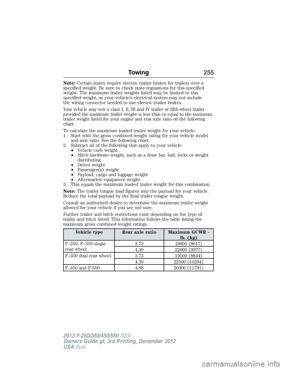
1. Start with the gross combined weight rating for your vehicle model
and axle ratio. See the following chart.
2. Subtract all of the following that apply to your vehicle:
•Vehicle curb weight
•Hitch hardware weight, such as a draw bar, ball, locks or weight
distributing
•Driver weight
•Passenger(s) weight
•Payload, cargo and luggage weight
•Aftermarket equipment weight.
3. This equals the maximum loaded trailer weight for this combination.
Note:The trailer tongue load figures into the payload for your vehicle.
Reduce the total payload by the final trailer tongue weight.
Consult an authorized dealer to determine the maximum trailer weight
allowed for your vehicle if you are not sure.
Further trailer and hitch restrictions exist depending on the type of
trailer and hitch listed. This information follows the table listing the
maximum gross combined weight ratings.
Vehicle type Rear axle ratio Maximum GCWR -
lb. (kg)
F–250, F–350 single
rear wheel3.73 19000 (8617)
4.30 22000 (9977)
F–350 dual rear wheel 3.73 19500 (8844)
4.30 22500 (10204)
F–450 and F-550 4.88 26000 (11791)
Towing255
2013 F-250/350/450/550(f23)
Owners Guide gf, 3rd Printing, December 2012
USA(fus)
Page 258 of 577
3. Securely attach the loaded trailer to your vehicle without the
weight-distributing bars connected.
4. Measure the height to the top of your vehicle’s front wheel opening
on the fender a second time. This is H2.
5. Install and adjust the tension in the weight-distributing bars so that
the height of your vehicle’s front wheel opening on the fender is
approximately halfway between H1 and H2.
6. Check that the trailer is level or slightly nose down toward your
vehicle. If not, adjust the ball height accordingly and repeat
Steps 2–6.
Once the trailer is level or slightly nose down toward the vehicle:
•Lock the bar tension adjuster in place.
•Check that the trailer tongue securely attaches and locks onto the
hitch.
•Install safety chains, lighting, and trailer brake controls as required by
law or the trailer manufacturer.
Fifth-Wheel Trailer Hitch (If Equipped)
WARNING:The mounting pads in the bed are specifically
designed for certain fifth-wheel trailer hitches and gooseneck ball
hitches. Do not use these mounting pads for other purposes. Doing so
could result in vehicle structural damage, loss of vehicle control, and
personal injury. Contact an authorized dealer to purchase gooseneck
and fifth-wheel hitches that are compatible with your vehicle.
WARNING:Towing trailers beyond the maximum limit of the
towing system could result in vehicle structural damage, loss of
vehicle control and personal injury.
WARNING:The hitch rating listed on the trailer hitch label is
the maximum possible trailer rating. To find the maximum trailer
weight allowed for your specific vehicle, consult an authorized dealer or
theRV & Trailer Towing Guideprovided by an authorized dealer.
Your vehicle may be equipped with a fifth-wheel prep package. This
package enables your vehicle to accept certain fifth-wheel trailer hitches
and gooseneck ball hitches. The fifth-wheel trailer hitch attaches to the
four mounting pads in the pick-up bed. An optional 7–pin trailer wiring
connector may be in the bed as well. The gooseneck ball hitch is a separate
mounting pad from the fifth-wheel hitch, located in the center of the bed.
Towing257
2013 F-250/350/450/550(f23)
Owners Guide gf, 3rd Printing, December 2012
USA(fus)
Page 260 of 577
Integrated Trailer Brake Controller (If Equipped)
WARNING:The Ford TBC has been verified to be compatible with
trailers having electric-actuated drum brakes (one to four axles)
and some electric-over-hydraulic (EOH) brakes. It will not activate
hydraulic surge-style trailer brakes. It is the responsibility of the customer
to ensure that the trailer brakes are adjusted appropriately, functioning
normally and all electric connections are properly made. Failure to do so
may result in loss of vehicle control, crash or serious injury.
When used properly, the trailer brake controller assists in smooth
and effective trailer braking by powering the trailer’s electric or
electric-over-hydraulic brakes with a proportional output based on the
towing vehicle’s brake pressure.
Ford has tested the trailer brake controller to be compatible with several
major brands of electric-over-hydraulic trailer brakes. Contact an
authorized dealer for information on which brands you can use.
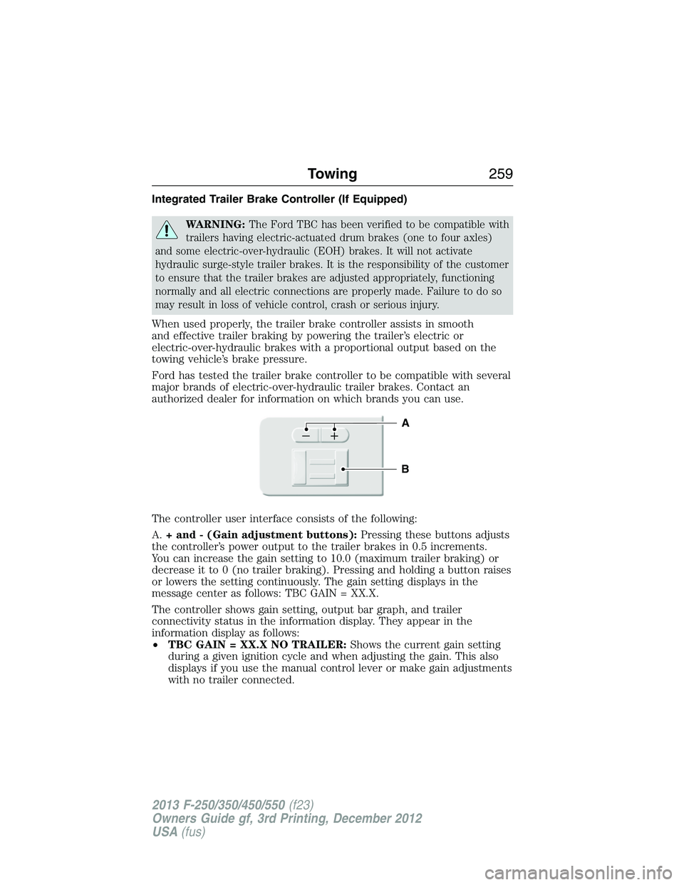
The controller user interface consists of the following:
A.+ and - (Gain adjustment buttons):Pressing these buttons adjusts
the controller’s power output to the trailer brakes in 0.5 increments.
You can increase the gain setting to 10.0 (maximum trailer braking) or
decrease it to 0 (no trailer braking). Pressing and holding a button raises
or lowers the setting continuously. The gain setting displays in the
message center as follows: TBC GAIN = XX.X.
The controller shows gain setting, output bar graph, and trailer
connectivity status in the information display. They appear in the
information display as follows:
•TBC GAIN = XX.X NO TRAILER:Shows the current gain setting
during a given ignition cycle and when adjusting the gain. This also
displays if you use the manual control lever or make gain adjustments
with no trailer connected.
B
A
Towing259
2013 F-250/350/450/550(f23)
Owners Guide gf, 3rd Printing, December 2012
USA(fus)
Page 261 of 577
•TBC GAIN = XX.X OUTPUT=//////:Displays when you push
your vehicle’s brake pedal, or when you use the manual control. Bar
indicators illuminate in the information display to indicate the amount
of power going to the trailer brakes relative to the brake pedal or
manual control input. One bar indicates the least amount of output;
six bars indicate maximum output.
•TRAILER CONNECTED:Displays when the system senses a
correct trailer wiring connection (a trailer with electric trailer brakes)
during a given ignition cycle.
•TRAILER DISCONNECTED:Displays, accompanied by a single
audible chime, when the system senses a trailer connection and then
a disconnection, either intentional or unintentional, during a given
ignition cycle. It also displays if a truck or trailer-wiring fault occurs
causing the trailer to appear disconnected. This message can also
display if you use the manual control lever without a trailer
connected.
B.Manual control lever:Slide the control lever to the left to turn
on the trailer’s electric brakes independent of the tow vehicle’s brakes.
See the followingProcedure for adjusting gainsection for instructions
on proper use of this feature. If you use the manual control while the
brake is also applied, the greater of the two inputs determines the power
sent to the trailer brakes.
•Stop lamps:Using the manual control lever illuminates both the
trailer brake lamps and your vehicle brake lamps except the center
high-mount stop lamp, if you make the proper electrical connection
to the trailer. Pressing your vehicle brake pedal also illuminates both
trailer and vehicle brake lamps.
Procedure for Adjusting Gain
Note:Only perform this procedure in a traffic-free environment at
speeds of approximately 20–25 mph (30–40 km/h).
The gain setting sets the trailer brake controller for the specific towing
condition. You should change the setting as towing conditions change.
Changes to towing conditions include trailer load, vehicle load, road
conditions and weather.
260Towing
2013 F-250/350/450/550(f23)
Owners Guide gf, 3rd Printing, December 2012
USA(fus)
Page 271 of 577
![FORD F250 2013 Owners Manual •Carry unnecessary weight (approximately 1 mpg [0.4 km/L] is lost for
every 400 pounds [180 kilograms] of weight carried).
•Add particular accessories to your vehicle (e.g.; bug deflectors,
rollba FORD F250 2013 Owners Manual •Carry unnecessary weight (approximately 1 mpg [0.4 km/L] is lost for
every 400 pounds [180 kilograms] of weight carried).
•Add particular accessories to your vehicle (e.g.; bug deflectors,
rollba](/manual-img/11/58774/w960_58774-270.png)
•Carry unnecessary weight (approximately 1 mpg [0.4 km/L] is lost for
every 400 pounds [180 kilograms] of weight carried).
•Add particular accessories to your vehicle (e.g.; bug deflectors,
rollbars or light bars, running boards, ski racks).
•Drive with the wheels out of alignment.
Conditions
•Heavily loading a vehicle or towing a trailer may reduce fuel economy
at any speed.
•Carrying unnecessary weight may reduce fuel economy (approximately
1 mpg [0.4 km/L] is lost for every 400 lb [180 kg] of weight carried).
•Adding certain accessories to your vehicle (for example bug
deflectors, rollbars/light bars, running boards, ski/luggage racks) may
reduce fuel economy.
•To maximize the fuel economy, drive with the tonneau cover installed
(if equipped).
•Using fuel blended with alcohol may lower fuel economy.
•Fuel economy may decrease with lower temperatures during the first
8–10 miles (12–16 km) of driving.
•Driving on flat terrain offers improved fuel economy as compared to
driving on hilly terrain.
•Transmissions give their best fuel economy when operated in the top
cruise gear and with steady pressure on the gas pedal.
•Four-wheel-drive operation (if equipped) is less fuel efficient than
two-wheel-drive operation.
•Close windows for high speed driving.
DRIVING THROUGH WATER
Note:If you drove through deep water, check the transmission and
engine fluid. If water is found, replace the fluid.
Do not drive quickly through standing water, especially if the depth is
unknown. Traction or brake capability may be limited and if the ignition
system gets wet, your engine may stall. Water may also enter your
engine’s air intake and severely damage your engine.
270Driving Hints
2013 F-250/350/450/550(f23)
Owners Guide gf, 3rd Printing, December 2012
USA(fus)
Page 293 of 577
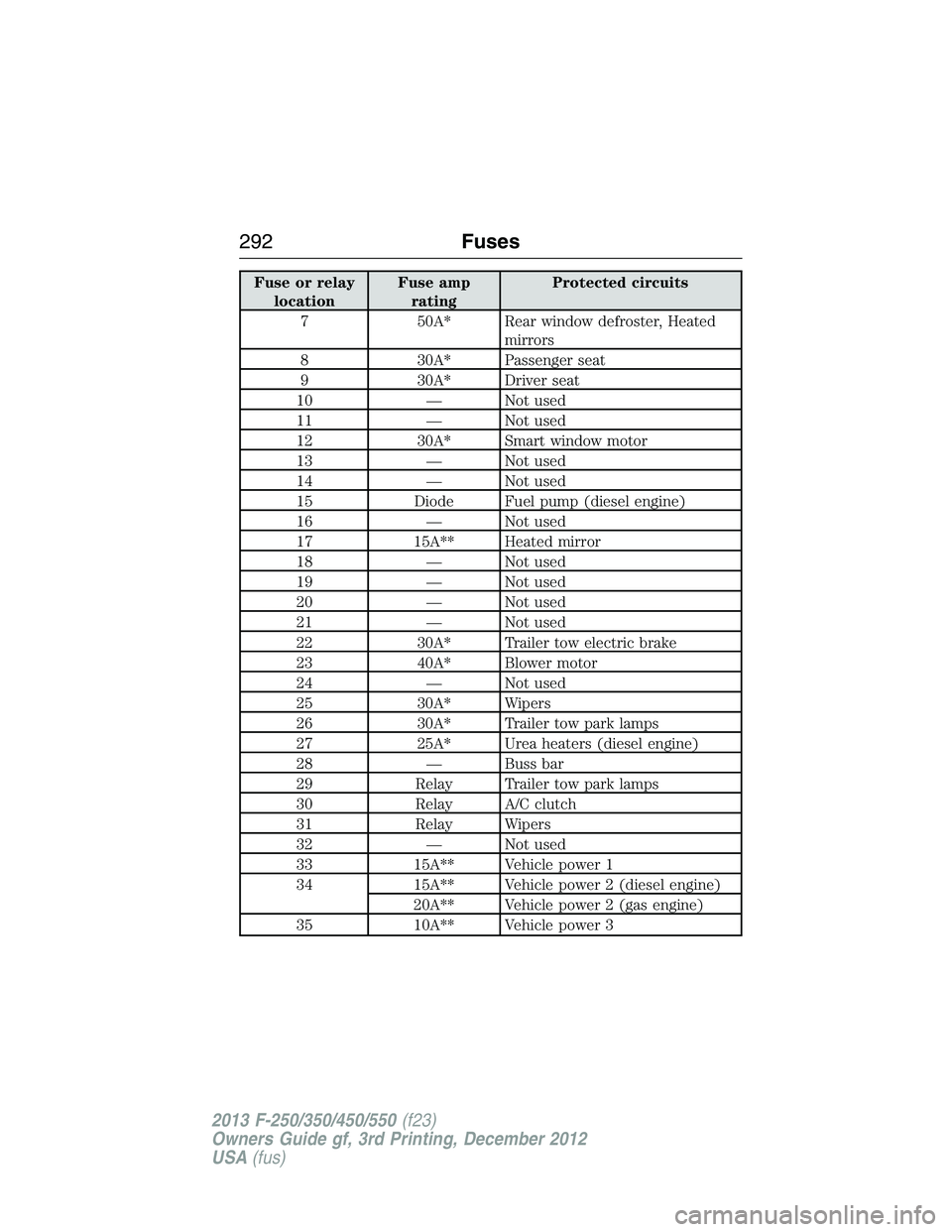
Fuse or relay
locationFuse amp
ratingProtected circuits
7 50A* Rear window defroster, Heated
mirrors
8 30A* Passenger seat
9 30A* Driver seat
10 — Not used
11 — Not used
12 30A* Smart window motor
13 — Not used
14 — Not used
15 Diode Fuel pump (diesel engine)
16 — Not used
17 15A** Heated mirror
18 — Not used
19 — Not used
20 — Not used
21 — Not used
22 30A* Trailer tow electric brake
23 40A* Blower motor
24 — Not used
25 30A* Wipers
26 30A* Trailer tow park lamps
27 25A* Urea heaters (diesel engine)
28 — Buss bar
29 Relay Trailer tow park lamps
30 Relay A/C clutch
31 Relay Wipers
32 — Not used
33 15A** Vehicle power 1
34 15A** Vehicle power 2 (diesel engine)
20A** Vehicle power 2 (gas engine)
35 10A** Vehicle power 3
292Fuses
2013 F-250/350/450/550(f23)
Owners Guide gf, 3rd Printing, December 2012
USA(fus)
Page 544 of 577
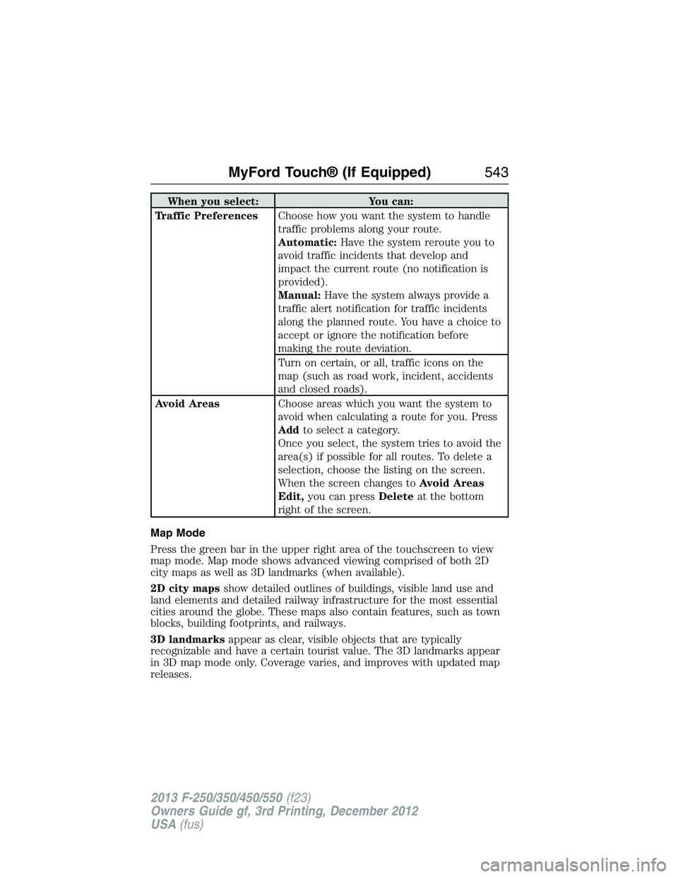
When you select: You can:
Traffic PreferencesChoose how you want the system to handle
traffic problems along your route.
Automatic:Have the system reroute you to
avoid traffic incidents that develop and
impact the current route (no notification is
provided).
Manual:Have the system always provide a
traffic alert notification for traffic incidents
along the planned route. You have a choice to
accept or ignore the notification before
making the route deviation.
Turn on certain, or all, traffic icons on the
map (such as road work, incident, accidents
and closed roads).
Avoid AreasChoose areas which you want the system to
avoid when calculating a route for you. Press
Addto select a category.
Once you select, the system tries to avoid the
area(s) if possible for all routes. To delete a
selection, choose the listing on the screen.
When the screen changes toAvoid Areas
Edit,you can pressDeleteat the bottom
right of the screen.
Map Mode
Press the green bar in the upper right area of the touchscreen to view
map mode. Map mode shows advanced viewing comprised of both 2D
city maps as well as 3D landmarks (when available).
2D city mapsshow detailed outlines of buildings, visible land use and
land elements and detailed railway infrastructure for the most essential
cities around the globe. These maps also contain features, such as town
blocks, building footprints, and railways.
3D landmarksappear as clear, visible objects that are typically
recognizable and have a certain tourist value. The 3D landmarks appear
in 3D map mode only. Coverage varies, and improves with updated map
releases.
MyFord Touch® (If Equipped)543
2013 F-250/350/450/550(f23)
Owners Guide gf, 3rd Printing, December 2012
USA(fus)