2013 FORD F250 instrument panel
[x] Cancel search: instrument panelPage 152 of 577

To aid in side window defogging and demisting in cold or humid weather:
1. Select Floor/Panel.
2. Select A/C.
3. Adjust the temperature control to maintain comfort.
4. Set the fan speed to the highest setting.
5. Direct the outer instrument panel vents toward the side windows.
6. To increase airflow to the outer instrument panel vents, close the
vents located in the middle of the instrument panel.
Dual Zone Automatic Temperature Control
•To reduce fog build-up on the windshield during humid weather, select
Defrost. Temperature and fan speed can also be increased to improve
clearing.
•To reduce humidity build-up inside the vehicle, do not drive with the
system off or with recirculated air engaged.
•Do not put objects under the front seats that will interfere with the
airflow to the back seats.
•Remove any snow, ice or leaves from the air intake area at the base of
the windshield.
•To improve the A/C cool down, drive with the windows slightly open
for 2-3 minutes after start-up or until the vehicle has been aired out.
•A small amount of air may be felt from the floor vent regardless of the
air distribution setting that is selected.
During extreme high ambient temperatures when idling stationary for
extended periods of time in gear, it is recommended to run the A/C in
the MAX A/C mode, adjust the blower fan speed to the lowest setting
and put the vehicle’s transmission into positionPto continue to receive
cool air from your A/C system.
For maximum cooling performance in AUTO or panel mode, press
MAX A/C.
For maximum cooling performance in panel/floor mode:
1. Choose the A/C and recirc buttons.
2. Set the temperature to LO.
3. Set the fan to the highest blower setting.
To aid in side window defogging and demisting in cold or humid weather:
1. Select Floor/Panel.
2. Select A/C.
3. Adjust the temperature control to maintain comfort.
4. Set the fan speed to the highest setting.
Climate Control151
2013 F-250/350/450/550(f23)
Owners Guide gf, 3rd Printing, December 2012
USA(fus)
Page 153 of 577
5. Direct the outer instrument panel vents toward the side windows.
6. To increase airflow to the outer instrument panel vents, close the
vents located in the middle of the instrument panel.
HEATED WINDOWS AND MIRRORS (IF EQUIPPED)
Heated Rear Window
Note:The engine must be running to use this feature.
Note:If your vehicle is equipped with a sliding rear window, the feature
still operates when the window is opened.
Press the button to clear the rear window of thin ice and fog. Press
the button again within 10 minutes to switch it off. It switches off
automatically after 10 minutes, or when you switch the ignition off.
Do not use razor blades or other sharp objects to clean the inside
of the rear window or to remove decals from the inside of the
rear window. This may cause damage to the heated grid lines.
Your warranty does not cover this damage.
Heated Exterior Mirror (If Equipped)
Note:Do not remove ice from the mirrors with a scraper or attempt to
readjust the mirror glass that has frozen in place. These actions could
cause damage to the glass and mirrors.
Note:Do not clean the housing or glass of any mirror with harsh
abrasives, fuel or other petroleum-based cleaning products.
Both mirrors heat to remove ice, mist and fog when you turn the rear
window defroster on.
REMOTE START CLIMATE OPERATION (IF EQUIPPED)
The climate control system adjusts the cabin temperature during remote
start.
You cannot adjust the system during remote start operation. Turn the
ignition on to return the system to its previous settings. You can now
make adjustments. You will need to turn certain vehicle-dependent
features back on, such as:
•heated seats
•cooled seats
•heated steering wheel
•heated mirrors
•heated rear window.
152Climate Control
2013 F-250/350/450/550(f23)
Owners Guide gf, 3rd Printing, December 2012
USA(fus)
Page 180 of 577
Locations
Power points may be found:
•on the instrument panel (two locations).
•inside the center console storage compartment (if equipped).
•on the rear of the center console (if equipped).
•inside the 20-percent front seat console (if equipped).
•inside the rear under seat storage compartment (if equipped).
110 Volt AC Power Points (If Equipped)
WARNING:Do not keep electrical devices plugged in the power
point whenever the device is not in use. Do not use any extension
cord with the 110–volt AC power point since it will defeat the safety
protection design. Do not power multiple devices from your power point.
Doing so may cause the power point to overload and could result in fire
or serious injury.
Note:Always close the protective cap after using the power point
outlets.
Note:The power points will turn off after 13 minutes if the ignition is on
without the engine running. Keep the engine running to use the power
points.
Your 110–volt AC power point outlets are used for powering electrical
devices that require up to 150 watts. Exceeding the 150–watt limit will
cause the power points to cut off the power temporarily to provide
overload protection.
Auxiliary Power Points179
2013 F-250/350/450/550(f23)
Owners Guide gf, 3rd Printing, December 2012
USA(fus)
Page 181 of 577

Your vehicle may have more than
one power point, located:
•on the back of the center console
•on the instrument panel.
Your power points are not designed for the following electric appliances
and may prevent the appliances from working properly:
•Cathode ray tube type televisions
•Motor loads, such as vacuum cleaners, electric saws and other electric
power tools, compressor-driven refrigerators, etc.
•Measuring devices, which process precise data, such as medical
equipment, measuring equipment, etc.
•Other appliances requiring an extremely stable power supply:
microcomputer-controlled electric blankets, touch sensor lamps, etc.
Power points can switch to a fault mode when overloaded, overheated
or shorted. Unplug your device and turn the ignition off then on for
overloading and shorting conditions. Let the system cool off, then turn
the ignition off then on for an overheating condition.
Power points can provide power whenever the ignition is on and the
indicator lights are on. Each indicator light is located in the top left
corner of the power point.
When the indicator light is:
•on — power point is ready to supply power
•off — power point power supply is off; ignition is not on
•blinking — power point is in fault mode.
180Auxiliary Power Points
2013 F-250/350/450/550(f23)
Owners Guide gf, 3rd Printing, December 2012
USA(fus)
Page 211 of 577
Note:Auto-manual hub locks can be manually overridden by rotating the
hub lock control from AUTO to LOCK.
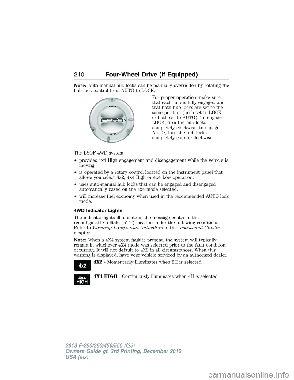
For proper operation, make sure
that each hub is fully engaged and
that both hub locks are set to the
same position (both set to LOCK
or both set to AUTO). To engage
LOCK, turn the hub locks
completely clockwise; to engage
AUTO, turn the hub locks
completely counterclockwise.
The ESOF 4WD system:
•provides 4x4 High engagement and disengagement while the vehicle is
moving.
•is operated by a rotary control located on the instrument panel that
allows you select 4x2, 4x4 High or 4x4 Low operation.
•uses auto-manual hub locks that can be engaged and disengaged
automatically based on the 4x4 mode selected.
•will increase fuel economy when used in the recommended AUTO lock
mode.
4WD Indicator Lights
The indicator lights illuminate in the message center in the
reconfigurable telltale (RTT) location under the following conditions.
Refer toWarning Lamps and Indicatorsin theInstrument Cluster
chapter.
Note:When a 4X4 system fault is present, the system will typically
remain in whichever 4X4 mode was selected prior to the fault condition
occurring. It will not default to 4X2 in all circumstances. When this
warning is displayed, have your vehicle serviced by an authorized dealer.
4X2- Momentarily illuminates when 2H is selected.
4X4 HIGH- Continuously illuminates when 4H is selected.
210Four-Wheel Drive (If Equipped)
2013 F-250/350/450/550(f23)
Owners Guide gf, 3rd Printing, December 2012
USA(fus)
Page 225 of 577
If the anti-lock brake system is disabled, normal braking is still
effective. If the brake warning lamp illuminates with the parking
brake released, have your brake system serviced immediately.
HINTS ON DRIVING WITH ANTI-LOCK BRAKES
When the system is operating, the brake pedal will pulse and may travel
further. Maintain pressure on the brake pedal. You may also hear a noise
from the system. This is normal.
The anti-lock braking system will not eliminate the dangers inherent
when:
•you drive too closely to the vehicle in front of you.
•your vehicle is hydroplaning.
•you take corners too fast.
•the road surface is poor.
PARKING BRAKE
WARNING:Always set the parking brake fully and make sure that
the transmission selector lever is securely latched in positionP.
To set the parking brake, press the parking brake pedal down until the
pedal stops.
The BRAKE warning lamp in the instrument cluster will illuminate and
remains illuminated until the parking brake is released.
To release, pull the brake release lever located at the lower left side of
the instrument panel.
If you are parking your vehicle on a grade or with a trailer, press and hold
the brake pedal down, then set the parking brake. There may be a little
vehicle movement as the parking brake sets to hold the vehicle’s weight.
This is normal and should be no reason for concern. If needed, press and
hold the service brake pedal down, then try reapplying the parking brake.
Chock the wheels if required. If the parking brake cannot hold the weight
of the vehicle, the parking brake may need to be serviced or the vehicle
may be overloaded.
224Brakes
2013 F-250/350/450/550(f23)
Owners Guide gf, 3rd Printing, December 2012
USA(fus)
Page 226 of 577
PRINCIPLES OF OPERATION
The traction control system helps avoid drive wheel spin and loss of
traction.
If your vehicle begins to slide, the system applies the brakes to individual
wheels and, when needed, reduces engine power at the same time. If the
wheels spin when accelerating on slippery or loose surfaces, the system
reduces engine power in order to increase traction.
USING TRACTION CONTROL
(Dual rear wheel vehicles only)
In certain situations (for example, stuck in snow or mud), turning the
traction control off may be beneficial as this allows the wheels to spin
with full engine power.
Turn the traction control system off by pressing the
stability control button located on the instrument
panel.
If the system cannot be turned off, see theMyKeychapter for more
information.
If traction control is on when your vehicle is put into four-wheel drive
mode (if equipped), the traction control system will be automatically
disabled. Traction control operation will resume when your vehicle is
placed back into two-wheel drive mode.
Engine Only Traction Control
(Dual rear wheel vehicles only)
Button functions TCS OFF indicator TCS
Default at start-up Not illuminated Enabled
Button pressed
momentarilyIlluminated Disabled
Button pressed again
after deactivationNot illuminated Enabled
Transfer case switched to
4WD
1Illuminated Disabled
1Engaging 4WD automatically disables TCS.
Traction Control225
2013 F-250/350/450/550(f23)
Owners Guide gf, 3rd Printing, December 2012
USA(fus)
Page 229 of 577
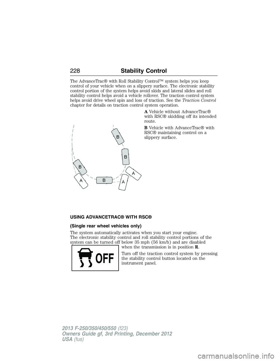
The AdvanceTrac® with Roll Stability Control™ system helps you keep
control of your vehicle when on a slippery surface. The electronic stability
control portion of the system helps avoid skids and lateral slides and roll
stability control helps avoid a vehicle rollover. The traction control system
helps avoid drive wheel spin and loss of traction. See theTraction Control
chapter for details on traction control system operation.
AVehicle without AdvanceTrac®
with RSC® skidding off its intended
route.
BVehicle with AdvanceTrac® with
RSC® maintaining control on a
slippery surface.
USING ADVANCETRAC® WITH RSC®
(Single rear wheel vehicles only)
The system automatically activates when you start your engine.
The electronic stability control and roll stability control portions of the
system can be turned off below 35 mph (56 km/h) and are disabled
when the transmission is in positionR.
Turn off the traction control system by pressing
the stability control button located on the
instrument panel.
228Stability Control
2013 F-250/350/450/550(f23)
Owners Guide gf, 3rd Printing, December 2012
USA(fus)