Page 279 of 577
HAZARD FLASHER CONTROL
Note:The hazard warning flashers will operate when the ignition is in
any position or if the key is not in the ignition. If used when the engine
is not running, the battery will lose charge. As a result, there may be
insufficient power to restart your engine.
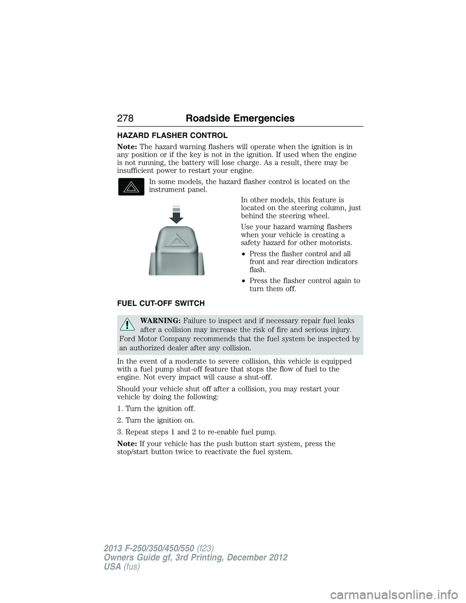
In some models, the hazard flasher control is located on the
instrument panel.
In other models, this feature is
located on the steering column, just
behind the steering wheel.
Use your hazard warning flashers
when your vehicle is creating a
safety hazard for other motorists.
•
Press the flasher control and all
front and rear direction indicators
flash.
•Press the flasher control again to
turn them off.
FUEL CUT-OFF SWITCH
WARNING:Failure to inspect and if necessary repair fuel leaks
after a collision may increase the risk of fire and serious injury.
Ford Motor Company recommends that the fuel system be inspected by
an authorized dealer after any collision.
In the event of a moderate to severe collision, this vehicle is equipped
with a fuel pump shut-off feature that stops the flow of fuel to the
engine. Not every impact will cause a shut-off.
Should your vehicle shut off after a collision, you may restart your
vehicle by doing the following:
1. Turn the ignition off.
2. Turn the ignition on.
3. Repeat steps 1 and 2 to re-enable fuel pump.
Note:If your vehicle has the push button start system, press the
stop/start button twice to reactivate the fuel system.
278Roadside Emergencies
2013 F-250/350/450/550(f23)
Owners Guide gf, 3rd Printing, December 2012
USA(fus)
Page 299 of 577
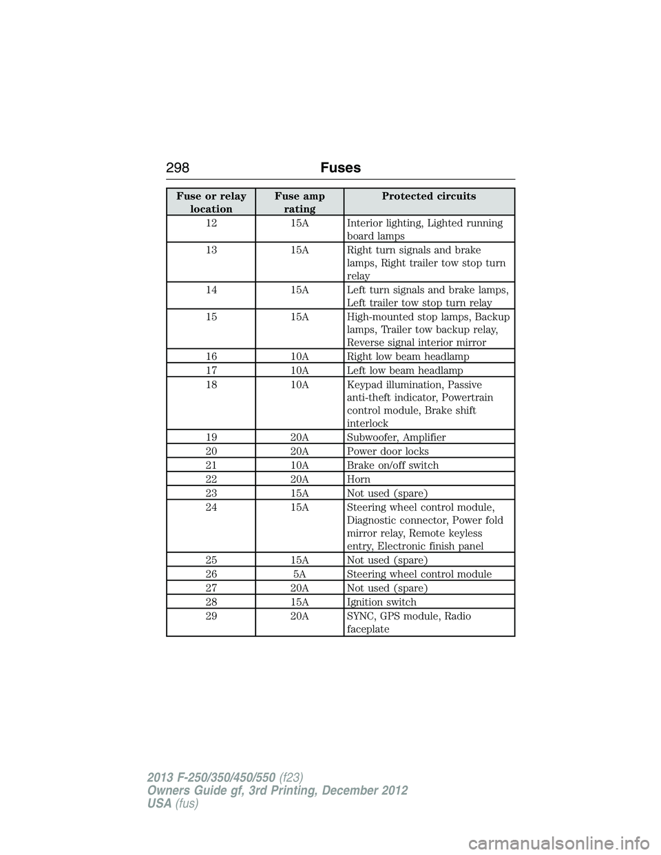
Fuse or relay
locationFuse amp
ratingProtected circuits
12 15A Interior lighting, Lighted running
board lamps
13 15A Right turn signals and brake
lamps, Right trailer tow stop turn
relay
14 15A Left turn signals and brake lamps,
Left trailer tow stop turn relay
15 15A High-mounted stop lamps, Backup
lamps, Trailer tow backup relay,
Reverse signal interior mirror
16 10A Right low beam headlamp
17 10A Left low beam headlamp
18 10A Keypad illumination, Passive
anti-theft indicator, Powertrain
control module, Brake shift
interlock
19 20A Subwoofer, Amplifier
20 20A Power door locks
21 10A Brake on/off switch
22 20A Horn
23 15A Not used (spare)
24 15A Steering wheel control module,
Diagnostic connector, Power fold
mirror relay, Remote keyless
entry, Electronic finish panel
25 15A Not used (spare)
26 5A Steering wheel control module
27 20A Not used (spare)
28 15A Ignition switch
29 20A SYNC, GPS module, Radio
faceplate
298Fuses
2013 F-250/350/450/550(f23)
Owners Guide gf, 3rd Printing, December 2012
USA(fus)
Page 300 of 577
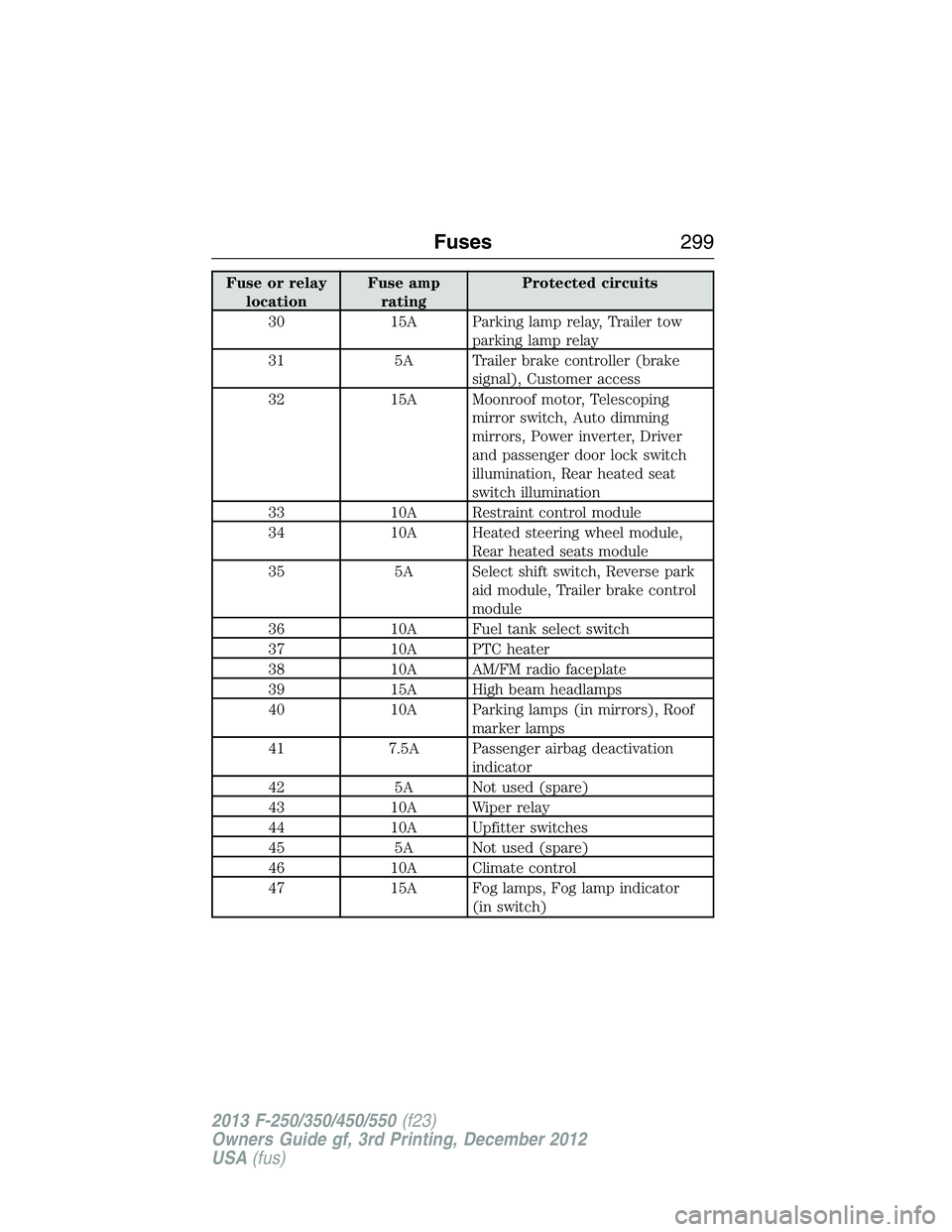
Fuse or relay
locationFuse amp
ratingProtected circuits
30 15A Parking lamp relay, Trailer tow
parking lamp relay
31 5A Trailer brake controller (brake
signal), Customer access
32 15A Moonroof motor, Telescoping
mirror switch, Auto dimming
mirrors, Power inverter, Driver
and passenger door lock switch
illumination, Rear heated seat
switch illumination
33 10A Restraint control module
34 10A Heated steering wheel module,
Rear heated seats module
35 5A Select shift switch, Reverse park
aid module, Trailer brake control
module
36 10A Fuel tank select switch
37 10A PTC heater
38 10A AM/FM radio faceplate
39 15A High beam headlamps
40 10A Parking lamps (in mirrors), Roof
marker lamps
41 7.5A Passenger airbag deactivation
indicator
42 5A Not used (spare)
43 10A Wiper relay
44 10A Upfitter switches
45 5A Not used (spare)
46 10A Climate control
47 15A Fog lamps, Fog lamp indicator
(in switch)
Fuses299
2013 F-250/350/450/550(f23)
Owners Guide gf, 3rd Printing, December 2012
USA(fus)
Page 302 of 577
There will also be one power lead
for each switch found as a blunt-cut
and sealed wire located below the
instrument panel and to the left of
the steering column.
They are coded as follows:
SwitchCircuit
NumberWire ColorFuse Amp
Rating
AUX 1 CAC05 Yellow 25A
AUX 2 CAC06 Green with
Brown Trace25A
AUX 3 CAC07 Violet with
Green Trace10A
AUX 4 CAC08 Brown 15A
More detailed information about upfitter switches can be found at
https://www.fleet.ford.com/truckbbas/.
Fuses301
2013 F-250/350/450/550(f23)
Owners Guide gf, 3rd Printing, December 2012
USA(fus)
Page 305 of 577
UNDER HOOD OVERVIEW
Refer to the diesel supplement for diesel engine component locations.
6.2L V8 Gasoline Engine
A. Windshield washer fluid reservoir
B. Engine oil dipstick
C. Automatic transmission fluid dipstick
D. Brake fluid reservoir
E. Engine coolant reservoir
F. Power distribution box
G. Air filter assembly
H. Power steering fluid reservoir
I. Engine oil filler cap
J. Battery
ADFEBC
GHIJ
304Maintenance
2013 F-250/350/450/550(f23)
Owners Guide gf, 3rd Printing, December 2012
USA(fus)
Page 306 of 577
6.8L V10 Gasoline Engine
A. Windshield washer fluid reservoir
B. Battery
C. Automatic transmission fluid dipstick
D. Engine oil filler cap
E. Engine oil dipstick
F. Power steering fluid reservoir
G. Brake fluid reservoir
H. Engine coolant reservoir
I. Air filter assembly
J. Power distribution box
ABCEHIJFDG
Maintenance305
2013 F-250/350/450/550(f23)
Owners Guide gf, 3rd Printing, December 2012
USA(fus)
Page 311 of 577
If you drive in extremely hot climates:
•It may be necessary to have a Ford authorized dealer decrease the
coolant concentration to 40%.
•A coolant concentration of 40% will provide improved overheat
protection. Engine coolant concentrations below 40% will decrease the
corrosion and freeze protection characteristics of the engine coolant
and may cause engine damage.
Vehicles driven year-round in non-extreme climates should use
prediluted engine coolant for optimum cooling system and engine
protection.
What You Should Know About Fail-Safe Cooling (If Equipped)
WARNING:If fail-safe cooling activates, pull off the road as soon
as safely possible and turn the engine off. The engine may
automatically shut off while driving without further indication.
If the engine coolant supply is depleted, this feature allows the vehicle to
be driven temporarily before incremental component damage is incurred.
The “fail-safe” distance depends on ambient temperatures, vehicle load
and terrain.
How Fail-Safe Cooling Works
If the engine begins to overheat:
•The engine coolant temperature gauge will move to the red (hot)
area.
•The information display will indicate the engine is overheating.
•The service engine soon indicator will illuminate.
If the engine reaches a preset over-temperature condition, the engine
will automatically switch to alternating cylinder operation. Each disabled
cylinder acts as an air pump and cools the engine.
When this occurs the vehicle will still operate. However:
•The engine power will be limited.
•The air conditioning system will be disabled.
Continued operation will increase the engine temperature and the engine
will completely shut down, causing steering and braking effort to
increase.
Once the engine temperature cools, the engine can be restarted. Take
your vehicle to an authorized dealer as soon as possible to minimize
engine damage.
310Maintenance
2013 F-250/350/450/550(f23)
Owners Guide gf, 3rd Printing, December 2012
USA(fus)
Page 318 of 577
BRAKE FLUID CHECK
Fluid levels between the MIN and MAX lines are within the normal
operating range; there is no need to add fluid. If the fluid levels are
outside of the normal operating range, the performance of the system
could be compromised; seek service from your authorized dealer
immediately.
POWER STEERING FLUID CHECK
Check the power steering fluid. Refer to yourScheduled Maintenance
Information.If adding fluid is necessary, use only MERCON® V ATF.
Note:This procedure is for vehicles with gasoline engines. Vehicles with
diesel engines are similar. Refer toUnder Hood Overviewin your diesel
supplement.
Check the fluid level when it is at ambient temperature, 20°F–80°F
(-7°C–25°C):
1. Check the fluid level in the reservoir. It should be between the MIN
and MAX range. Do not add fluid if the level is within this range.
2. If the fluid level is low. Add fluid to bring fluid level up to be between
the MIN and MAX range.
3. Start the engine.
4. While the engine idles, turn the steering wheel left and right several
times.
5. Turn the engine off.
6. Recheck the fluid level in the reservoir. Do not add fluid if the level is
between the MIN and MAX range.
7. If the fluid is low, add fluid in small amounts, continuously checking
the level until it is between the MIN and MAX range. Refer toCapacities
and Specificationsfor the proper fluid type. Be sure to put the cap
back on the reservoir.
FUEL FILTER
If equipped with a gasoline engine, your vehicle is equipped with a
lifetime fuel filter that is integrated with the fuel tank. Regular
maintenance or replacement is not needed.
If equipped with a diesel engine, refer to the diesel supplement.
Maintenance317
2013 F-250/350/450/550(f23)
Owners Guide gf, 3rd Printing, December 2012
USA(fus)