Page 593 of 683
ENGINE COMPARTMENT — 3.6L
1 — Air Filter 6 — Engine Coolant Reservoir
2 — Power Steering Fluid Reservoir 7 — Engine Oil Dipstick
3 — Brake Fluid Reservoir 8 — Engine Oil Fill
4 — Battery 9 — Coolant Pressure Cap
5 — Totally Integrated Power Module (Fuses) 10 — Washer Fluid Reservoir7
MAINTAINING YOUR VEHICLE 591
Page 595 of 683

Loose Fuel Filler Cap Message
If the vehicle diagnostic system determines that the fuel
filler cap is loose, improperly installed, or damaged, a
“gASCAP” message will display in the odometer or a
“CHECK GASCAP” message will be displayed in the
Electronic Vehicle Information Center (EVIC). Refer to
“Electronic Vehicle Information Center (EVIC)” in ”Un-
derstanding Your Instrument Panel” for further informa-
tion. Tighten the gas cap until a�clicking�sound is heard.
This is an indication that the gas cap is properly tight-
ened.
Press the odometer reset button to turn the message off.
If the problem persists, the message will appear the next
time the vehicle is started. This might indicate a damaged
cap. If the problem is detected twice in a row, the system
will turn on the MIL. Resolving the problem will turn the
MIL light off.
EMISSIONS INSPECTION AND MAINTENANCE
PROGRAMS
In some localities, it may be a legal requirement to pass
an inspection of your vehicle’s emissions control system.
Failure to pass could prevent vehicle registration.
For states that require an Inspection and Mainte-
nance (I/M), this check verifies the “Malfunction
Indicator Light (MIL)” is functioning and is not
on when the engine is running, and that the OBD II
system is ready for testing.
Normally, the OBD II system will be ready. The OBD II
system maynotbe ready if your vehicle was recently
serviced, recently had a dead battery or a battery replace-
ment. If the OBD II system should be determined not
ready for the I/M test, your vehicle may fail the test.
7
MAINTAINING YOUR VEHICLE 593
Page 596 of 683

Your vehicle has a simple ignition key-actuated test,
which you can use prior to going to the test station. To
check if your vehicle’s OBD II system is ready, you must
do the following:
1. Turn the ignition switch to the ON position, but do not
crank or start the engine.
2. If you crank or start the engine, you will have to start
this test over.
3. As soon as you turn the ignition switch to the ON
position, you will see the MIL symbol come on as part
of a normal bulb check.
4. Approximately 15 seconds later, one of two things will
happen:
•
The MIL will flash for about 10 seconds and then return
to being fully illuminated until you turn OFF the igni-
tion or start the engine. This means that your vehicle’s
OBD II system isnot readyand you shouldnotproceed
to the I/M station.
•The MIL will not flash at all and will remain fully
illuminated until you turn OFF the ignition or start the
engine. This means that your vehicle’s OBD II system
isreadyand you can proceed to the I/M station.
If your OBD II system isnot ready,you should see your
authorized dealer or repair facility. If your vehicle was
recently serviced or had a battery failure or replacement,
you may need to do nothing more than drive your
vehicle as you normally would in order for your OBD II
system to update. A recheck with the above test routine
may then indicate that the system is now ready.
Regardless of whether your vehicle’s OBD II system is
ready or not, if the MIL is illuminated during normal
vehicle operation you should have your vehicle serviced
before going to the I/M station. The I/M station can fail
your vehicle because the MIL is on with the engine
running.
594 MAINTAINING YOUR VEHICLE
Page 605 of 683

Maintenance-Free Battery
Your vehicle is equipped with a maintenance-free battery.
You will never have to add water, nor is periodic main-
tenance required.
WARNING!
•Battery fluid is a corrosive acid solution and can burn
or even blind you. Do not allow battery fluid to
contact your eyes, skin, or clothing. Do not lean over
a battery when attaching clamps. If acid splashes in
eyes or on skin, flush the area immediately with large
amounts of water. Refer to “Jump-Starting Proce-
dures” in “What To Do In Emergencies” for further
information.
•Battery gas is flammable and explosive. Keep
flame or sparks away from the battery. Do not use
a booster battery or any other booster source with
(Continued)
WARNING!(Continued)
an output greater than 12 Volts. Do not allow cable
clamps to touch each other.
•Battery posts, terminals, and related accessories
contain lead and lead compounds. Wash hands
after handling.
CAUTION!
•It is essential when replacing the cables on the
battery that the positive cable is attached to the
positive post and the negative cable is attached to
the negative post. Battery posts are marked posi-
tive (+) and negative (-) and are identified on the
battery case. Cable clamps should be tight on the
terminal posts and free of corrosion.
(Continued)
7
MAINTAINING YOUR VEHICLE 603
Page 606 of 683

CAUTION!(Continued)
•If a “fast charger” is used while the battery is in the
vehicle, disconnect both vehicle battery cables be-
fore connecting the charger to the battery. Do not
use a “fast charger” to provide starting voltage.
Air Conditioner Maintenance
For best possible performance, your air conditioner should
be checked and serviced by an authorized dealer at the
start of each warm season. This service should include
cleaning of the condenser fins and a performance test.
Drive belt tension should also be checked at this time.
CAUTION!
Do not use chemical flushes in your air conditioning
system as the chemicals can damage your air condi-
tioning components. Such damage is not covered by
the New Vehicle Limited Warranty.
WARNING!
•Use only refrigerants and compressor lubricants
approved by the manufacturer for your air condi-
tioning system. Some unapproved refrigerants are
flammable and can explode, injuring you. Other
unapproved refrigerants or lubricants can cause the
system to fail, requiring costly repairs. Refer to
Warranty Information Book, located on the DVD,
for further warranty information.
•The air conditioning system contains refrigerant
under high pressure. To avoid risk of personal
injury or damage to the system, adding refrigerant
or any repair requiring lines to be disconnected
should be done by an experienced technician.
604 MAINTAINING YOUR VEHICLE
Page 628 of 683
FUSES
Totally Integrated Power Module
The Totally Integrated Power Module is located in the
engine compartment near the battery. Refer to the appli-
cable “Engine Compartment” illustration in this section.
This center contains cartridge fuses and mini-fuses. A
label that identifies each component may be printed or
embossed on the inside of the cover.
Totally Integrated Power Module
626 MAINTAINING YOUR VEHICLE
Page 635 of 683

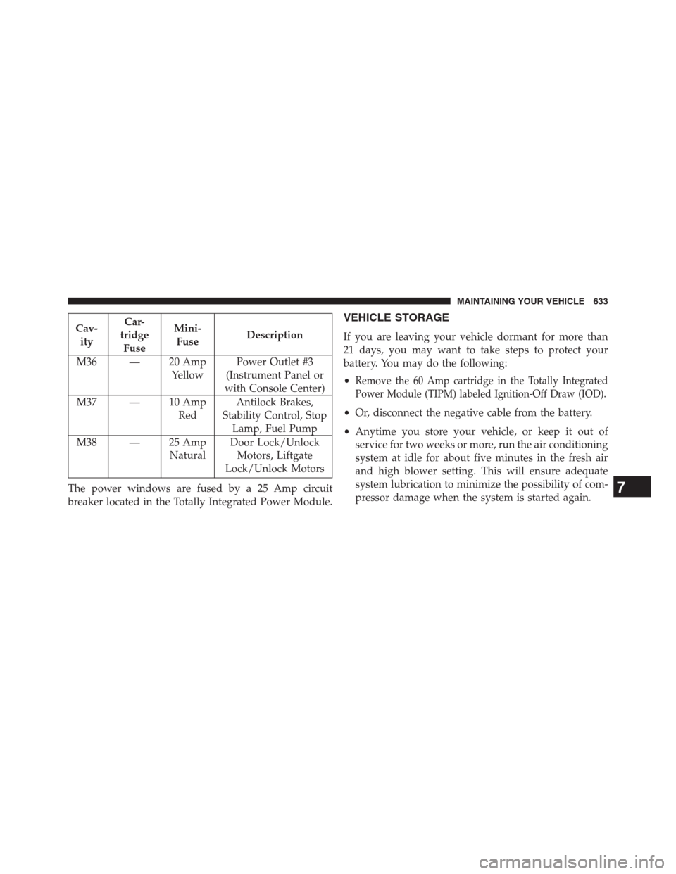
Cav-
ityCar-
tridge
FuseMini-
FuseDescription
M36 — 20 Amp
YellowPower Outlet #3
(Instrument Panel or
with Console Center)
M37 — 10 Amp
RedAntilock Brakes,
Stability Control, Stop
Lamp, Fuel Pump
M38 — 25 Amp
NaturalDoor Lock/Unlock
Motors, Liftgate
Lock/Unlock Motors
The power windows are fused by a 25 Amp circuit
breaker located in the Totally Integrated Power Module.VEHICLE STORAGE
If you are leaving your vehicle dormant for more than
21 days, you may want to take steps to protect your
battery. You may do the following:
•
Remove the 60 Amp cartridge in the Totally Integrated
Power Module (TIPM) labeled Ignition-Off Draw (IOD).
•Or, disconnect the negative cable from the battery.
•Anytime you store your vehicle, or keep it out of
service for two weeks or more, run the air conditioning
system at idle for about five minutes in the fresh air
and high blower setting. This will ensure adequate
system lubrication to minimize the possibility of com-
pressor damage when the system is started again.
7
MAINTAINING YOUR VEHICLE 633
Page 645 of 683
Required Maintenance Intervals.
Refer to the maintenance schedules on the following
page for the required maintenance intervals.
At Every Oil Change Interval As Indicated By Oil
Change Indicator System:
•Change oil and filter.
•Rotate the tires.Rotate at the first sign of irregu-
lar wear, even if it occurs before the oil indicator
system turns on.
•Inspect battery and clean and tighten terminals as
required.
At Every Oil Change Interval As Indicated By Oil
Change Indicator System:
•Inspect automatic transmission fluid if equipped
with dipstick.
•Inspect brake pads, shoes, rotors, drums, hoses
and park brake.
•Inspect engine cooling system protection and
hoses.
•Inspect exhaust system.
•Inspect engine air cleaner if using in dusty or
off-road conditions.
8
M
A
I
N
T
E
N
A
N
C
E
S
C
H
E
D
U
L
E
SMAINTENANCE SCHEDULES 643