2013 DODGE GRAND CARAVAN electrical
[x] Cancel search: electricalPage 466 of 683

ENGINE BLOCK HEATER — IF EQUIPPED
The engine block heater warms the engine, and permits
quicker starts in cold weather. Connect the cord to a
standard 110-115 Volt AC electrical outlet with a
grounded, three-wire extension cord.
The engine block heater must be plugged in at least one
hour to have an adequate warming effect on the engine.
The engine block heater cord is routed under the hood on
the driver’s side of the vehicle. It has a removable cap
that is located on the driver side of the Integrated Power
Module.
WARNING!
Remember to disconnect the engine block heater
cord before driving. Damage to the 110-115 Volt
electrical cord could cause electrocution.
AUTOMATIC TRANSMISSION
CAUTION!
Damage to the transmission may occur if the follow-
ing precautions are not observed:
•Shift into PARK only after the vehicle has come to
a complete stop.
•Shift into or out of REVERSE only after the vehicle
has come to a complete stop and the engine is at
idle speed.
•Do not shift between PARK, REVERSE, NEU-
TRAL, or DRIVE when the engine is above idle
speed.
•Before shifting into any gear, make sure your foot
is firmly pressing the brake pedal.
NOTE:You must press and hold the brake pedal while
shifting out of PARK.
464 STARTING AND OPERATING
Page 555 of 683

WARNING!(Continued)
•Towing any trailer will increase your stopping dis-
tance. When towing you should allow for additional
space between your vehicle and the vehicle in front of
you. Failure to do so could result in a collision.
Towing Requirements – Trailer Lights And Wiring
Whenever you pull a trailer, regardless of the trailer size,
stoplights and turn signals on the trailer are required for
motoring safety.
The Trailer Tow Package may include a four- and seven-
pin wiring harness. Use a factory approved trailer har-
ness and connector.
NOTE:Do not cut or splice wiring into the vehicles
wiring harness.
The electrical connections are all complete to the vehicle
but you must mate the harness to a trailer connector.
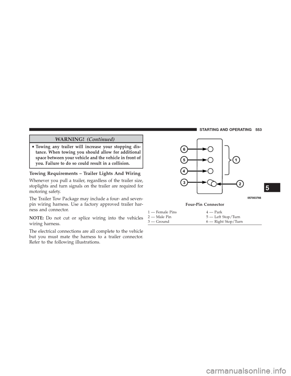
Refer to the following illustrations.
Four-Pin Connector
1 — Female Pins 4 — Park
2 — Male Pin 5 — Left Stop/Turn
3 — Ground 6 — Right Stop/Turn
5
STARTING AND OPERATING 553
Page 581 of 683

WARNING!
To avoid the risk of forcing the vehicle off the jack,
do not tighten the wheel nuts fully until the vehicle
has been lowered. Failure to follow this warning may
result in personal injury.
3. Lower the vehicle to the ground by turning the jack
handle counterclockwise.
4.
Finish tightening the lug nuts. Push down on the
wrench while at the end of the handle for increased
leverage. Tighten the lug nuts in a star pattern until each
nut has been tightened twice. The correct tightness of
each lug nut is 100 ft/lbs (135 N·m). If in doubt about
the correct tightness, have them checked with a torque
wrench by your authorized dealer or service station.
5. After 25 miles (40 km) check the lug nut torque with a
torque wrench to ensure that all lug nuts are properly
seated against the wheel.
JUMP-STARTING
If your vehicle has a discharged battery it can be jump-
started using a set of jumper cables and a battery in
another vehicle or by using a portable battery booster
pack. Jump-starting can be dangerous if done improperly
so please follow the procedures in this section carefully.
NOTE:When using a portable battery booster pack
follow the manufacturer ’s operating instructions and
precautions.
CAUTION!
Do not use a portable battery booster pack or any
other booster source with a system voltage greater
than 12 Volts or damage to the battery, starter motor,
alternator or electrical system may occur.
6
WHAT TO DO IN EMERGENCIES 579
Page 583 of 683

WARNING!
•Take care to avoid the radiator cooling fan when-
ever the hood is raised. It can start anytime the
ignition switch is ON. You can be injured by
moving fan blades.
•Remove any metal jewelry such as rings, watch
bands and bracelets that could make an inadvertent
electrical contact. You could be seriously injured.
•Batteries contain sulfuric acid that can burn your
skin or eyes and generate hydrogen gas which is
flammable and explosive. Keep open flames or
sparks away from the battery.
1. Set the parking brake, shift the automatic transmission
into PARK and turn the ignition to LOCK.
2. Turn off the heater, radio, and all unnecessary electri-
cal accessories.3. If using another vehicle to jump-start the battery, park
the vehicle within the jumper cables reach, set the
parking brake and make sure the ignition is OFF.
WARNING!
Do not allow vehicles to touch each other as this
could establish a ground connection and personal
injury could result.
Jump-Starting Procedure
WARNING!
Failure to follow this procedure could result in per-
sonal injury or property damage due to battery ex-
plosion.
6
WHAT TO DO IN EMERGENCIES 581
Page 584 of 683

CAUTION!
Failure to follow these procedures could result in
damage to the charging system of the booster vehicle
or the discharged vehicle.
1. Connect the positive(+)end of the jumper cable to the
positive(+)post of the discharged vehicle.
2. Connect the opposite end of the positive(+)jumper
cable to the positive(+)post of the booster battery.
3. Connect the negative end(-)of the jumper cable to the
negative(-)post of the booster battery.
4. Connect the opposite end of the negative(-)jumper
cable to a good engine ground (exposed metal part of
the discharged vehicle’s engine) away from the battery
and the fuel injection system.
WARNING!
Do not connect the cable to the negative post (-) of the
discharged battery. The resulting electrical spark
could cause the battery to explode and could result in
personal injury.
5. Start the engine in the vehicle that has the booster
battery, let the engine idle a few minutes, and then
start the engine in the vehicle with the discharged
battery. Once the engine is started, remove the jumper
cables in the reverse sequence:
6. Disconnect the negative(-)jumper cable from the
negative(-)post of the vehicle with the discharged
battery.
7. Disconnect the negative end(-)of the jumper cable
from the negative(-)post of the booster battery.
582 WHAT TO DO IN EMERGENCIES
Page 629 of 683

CAUTION!
•When installing the Totally Integrated Power Mod-
ule cover, it is important to ensure the cover is
properly positioned and fully latched. Failure to do
so may allow water to get into the Integrated Power
Module, and possibly result in a electrical system
failure.
•When replacing a blown fuse, it is important to use
only a fuse having the correct amperage rating. The
use of a fuse with a rating other than indicated may
result in a dangerous electrical system overload. If
a properly rated fuse continues to blow, it indicates
a problem in the circuit that must be corrected.The numbers inside the TIPM cover correspond to the
following table.
Cav-
ityCar-
tridge
FuseMini-
FuseDescription
J1 40 Amp
Green— Power Folding Seat
J2 30 Amp
Pink—
Power Liftgate Module
J3 30 Amp
Pink— Rear Door Module
J4 25 Amp
Natural— Driver Door Node
J5 25 Amp
Natural— Passenger Door Node
J6 40 Amp
Green— Antilock Brakes
Pump/Stability
Control System
7
MAINTAINING YOUR VEHICLE 627
Page 668 of 683

Electrical Power Outlets.....................269
Electric Remote Mirrors.....................133
Electronic Brake Control System...............486
Brake Assist System.....................487
Electronic Speed Control (Cruise Control)........237
Electronic Stability Control (ESC)..............488
Electronic Vehicle Information Center (EVIC)......325
Emergency, In Case of
Hazard Warning Flasher..................560
Jacking...............................561
Jump Starting..........................579
Overheating...........................560
Emission Control System Maintenance..........593
Engine
Air Cleaner...........................599
Block Heater..........................464
Break-In Recommendations................116
Checking Oil Level......................597
Compartment..........................591Compartment Identification................591
Coolant (Antifreeze).....................609
Cooling..............................608
Exhaust Gas Caution.....................117
Flooded, Starting.......................462
Fuel Requirements......................528
Oil..................................597
Oil Selection...........................597
Oil Synthetic..........................598
Overheating...........................560
Starting..............................461
Temperature Gauge......................322
Engine Oil Viscosity.......................598
Engine Oil Viscosity Chart...................598
Enhanced Accident Response Feature............85
Entry System, Illuminated....................20
Ethanol................................529
Event Data Recorder........................88
Exhaust Gas Caution........................55
666 INDEX
Page 675 of 683

Odometer...............................312
Oil Change Indicator.......................313
Oil Change Indicator, Reset..................313
Oil, Engine..............................597
Capacity.............................638
Change Interval........................597
Checking.............................597
Disposal..............................599
Filter................................599
Filter Disposal.........................599
Identification Logo......................598
Materials Added to......................599
Recommendation.......................597
Synthetic.............................598
Viscosity.............................598
Oil Filter, Selection........................599
Onboard Diagnostic System..................592
Opener, Garage Door (HomeLink®)............256
Operator Manual (Owner’s Manual).............4Outside Rearview Mirrors...................130
Overhead Console.........................252
Overhead Travel Information Center............252
Overheating, Engine.......................322
Owner’s Manual (Operator Manual).............4
Paint Care..............................619
Panic Alarm..............................25
Parking Brake............................481
Park Sense System, Rear....................241
Pedals, Adjustable.........................235
Personal Settings..........................342
Pets, Transporting.........................112
Placard, Tire and Loading Information..........502
Power
Door Locks............................37
Lift Gate..............................53
Mirrors..............................133
Outlet (Auxiliary Electrical Outlet)
...........26910
INDEX 673