Page 90 of 683

Air Bag Warning Light
You will want to have the air bags ready to
inflate for your protection in a collision. The Air
Bag Warning Light monitors the internal circuits
and interconnecting wiring associated with air
bag system electrical components. While the air bag system
is designed to be maintenance free, if any of the following
occurs, have an authorized dealer service the air bag
system immediately.
•The Air Bag Warning Light does not come on for
approximately four to eight seconds when the ignition
switch is first turned to ON/RUN.
•The Air Bag Warning Light remains on after the
approximate four to eight-second interval.
•The Air Bag Warning Light comes on intermittently or
remains on while driving.NOTE:If the speedometer, tachometer, or any engine
related gauges are not working, the Occupant Restraint
Controller (ORC) may also be disabled. The air bags may
not be ready to inflate for your protection. Promptly
check the fuse block for blown fuses. Refer to the label
located on the inside of the fuse block cover for the
proper air bag fuses. See your authorized dealer if the
fuse is good.
Event Data Recorder (EDR)
This vehicle is equipped with an event data recorder
(EDR). The main purpose of an EDR is to record, in
certain crash or near crash-like situations, such as an air
bag deployment or hitting a road obstacle, data that will
assist in understanding how a vehicle’s systems per-
formed. The EDR is designed to record data related to
vehicle dynamics and safety systems for a short period of
88 THINGS TO KNOW BEFORE STARTING YOUR VEHICLE
Page 130 of 683

▫Venting Sunroof — Express..............267
▫Sunshade Operation....................268
▫Wind Buffeting.......................268
▫Sunroof Maintenance...................268
▫Ignition Off Operation..................268
▫Sunroof Fully Closed...................269
�ELECTRICAL POWER OUTLETS — IF
EQUIPPED...........................269
�POWER INVERTER — IF EQUIPPED.........273
�CUPHOLDERS........................274
▫Instrument Panel Cupholders.............275
▫Super Console — If Equipped.............275
▫Premium Console Cupholders — If
Equipped...........................276▫Interior Bottle Holders..................277
▫Smoker’s Package Kit — If Equipped.......278
�STORAGE............................278
▫Glove Compartments..................278
▫Door Trim Panel Storage................280
▫Driver Seatback Storage — If Equipped......280
▫Umbrella Holder.....................281
▫Second Row Seat Storage Bins — If
Equipped...........................281
▫Storage Bin Safety Warning...............282
▫Coat Hooks.........................284
▫Cargo Area Storage....................284
128 UNDERSTANDING THE FEATURES OF YOUR VEHICLE
Page 271 of 683
Sunroof Fully Closed
Press the switch forward and release to ensure that the
sunroof is fully closed.
ELECTRICAL POWER OUTLETS — IF EQUIPPED
Two 12 Volt (13 Amp) power outlets are located on the
lower instrument panel, below the open storage bin. The
driver-side power outlet is controlled by the ignition
switch and the passenger-side power outlet is connected
directly to the battery. The driver-side power outlet will
also operate a conventional cigar lighter unit (if equipped
with an optional Smoker’s Package).
NOTE:To ensure proper operation a MOPAR® cigar
knob and element must be used.
Instrument Panel Outlets
3
UNDERSTANDING THE FEATURES OF YOUR VEHICLE 269
Page 276 of 683

The power inverter switch is located on the instrument
panel below the climate controls.
To turn on the power outlet, press the switch once. Press
the switch a second time to turn the power outlet off.
This outlet can power cellular phones, electronics and
other low power devices requiring power up to
150 Watts. Certain high-end video games, such as Play-
station3 and XBox360 will exceed this power limit, as will
most power tools.
The power inverter is designed with built-in overload
protection. If the power rating of 150 Watts is exceeded,
the power inverter will automatically shut down. Once
the electrical device has been removed from the outlet theinverter should automatically reset. If the power rating
exceeds approximately 170 Watts, the power inverter
may have to be reset manually. To reset the inverter
manually press the power inverter button OFF and ON.
To avoid overloading the circuit, check the power ratings
on electrical devices prior to using the inverter.
CUPHOLDERS
There are cupholders located throughout the interior. All
liners are removable for cleaning. Pull the flexible liner
from the cupholder drawer or tray starting at one edge
for easy removal. Refer to “Cleaning The Instrument
Panel Cupholders” in “Maintaining Your Vehicle” for
further information.
274 UNDERSTANDING THE FEATURES OF YOUR VEHICLE
Page 325 of 683

22. Charging System Light
This light shows the status of the electrical charg-
ing system. The light should come on when the
ignition switch is first turned to ON/RUN and remain on
briefly as a bulb check. If the light stays on or comes on
while driving, turn off some of the vehicle’s non-essential
electrical devices or increase engine speed (if at idle).
If the charging system light remains on, it means that the
vehicle is experiencing a problem with the charging
system. Obtain SERVICE IMMEDIATELY. See an autho-
rized dealer.
If jump starting is required, refer to “Jump Starting
Procedures” in “What To Do In Emergencies”.23. Oil Pressure Warning Light
This light indicates low engine oil pressure.
The light should turn on momentarily when the engine is
started. If the light turns on while driving, stop the
vehicle and shut off the engine as soon as possible.
A chime will sound when this light turns on.
Do not operate the vehicle until the cause is corrected.
This light does not indicate how much oil is in the engine.
The engine oil level must be checked under the hood.
24. Engine Temperature Warning Light
This light warns of an overheated engine condi-
tion. As engine coolant temperatures rise and the
gauge approachesH, this indicator will illuminate and a
single chime will sound after reaching a set threshold.
Further overheating will cause the temperature gauge to
passH, a continuous chime will occur until the engine is
allowed to cool.
4
UNDERSTANDING YOUR INSTRUMENT PANEL 323
Page 335 of 683

•Charging System Light
This light shows the status of the electrical charg-
ing system. The light should come on when the
ignition switch is first turned ON and remain on briefly
as a bulb check. If the light stays on or comes on while
driving, turn off some of the vehicle’s non-essential
electrical devices or increase engine speed (if at idle). If
the charging system light remains on, it means that the
vehicle is experiencing a problem with the charging
system. Obtain SERVICE IMMEDIATELY. See an autho-
rized dealer.
If jump starting is required, refer to “Jump Starting
Procedures” in “What To Do In Emergencies”.•Electronic Throttle Control (ETC) Light
This light informs you of a problem with the
Electronic Throttle Control (ETC) system. The
light will come on when the ignition is first
turned ON and remain on briefly as a bulb
check. If the light does not come on during starting, have
the system checked by an authorized dealer.
If a problem is detected, the light will come on while the
engine is running. Cycle the ignition key when the
vehicle has completely stopped and the shift lever is
placed in the PARK position. The light should turn off.
If the light remains lit with the engine running, your
vehicle will usually be drivable. However, see an autho-
rized dealer for service as soon as possible. If the light is
flashing when the engine is running, immediate service is
required. You may experience reduced performance, an
elevated/rough idle or engine stall and your vehicle may
require towing.
4
UNDERSTANDING YOUR INSTRUMENT PANEL 333
Page 440 of 683

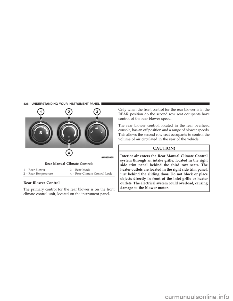
Rear Blower Control
The primary control for the rear blower is on the front
climate control unit, located on the instrument panel.Only when the front control for the rear blower is in the
REARposition do the second row seat occupants have
control of the rear blower speed.
The rear blower control, located in the rear overhead
console, has an off position and a range of blower speeds.
This allows the second row seat occupants to control the
volume of air circulated in the rear of the vehicle.
CAUTION!
Interior air enters the Rear Manual Climate Control
system through an intake grille, located in the right
side trim panel behind the third row seats. The
heater outlets are located in the right side trim panel,
just behind the sliding door. Do not block or place
objects directly in front of the inlet grille or heater
outlets. The electrical system could overload, causing
damage to the blower motor.
Rear Manual Climate Controls
1 – Rear Blower 3 – Rear Mode
2 – Rear Temperature 4 – Rear Climate Control Lock 438 UNDERSTANDING YOUR INSTRUMENT PANEL
Page 452 of 683

NOTE:
•It is not necessary to move the temperature settings for
cold or hot vehicles. The system automatically adjusts
the temperature, mode and fan speed to provide
comfort as quickly as possible.
•The temperature can be displayed in English or Metric
units by selecting the “Display Units of Measure in”
customer-programmable feature. Refer to the “Elec-
tronic Vehicle Information Center (EVIC) — Customer-
Programmable Features” in this Section.Rear Blower Control
The rear blower control knob can be manually set to off,
or any fixed blower speed, by rotating the knob from low
to high. This allows the rear seat occupants to control the
volume of air circulated in the rear of the vehicle.
CAUTION!
Interior air enters the Rear Automatic Temperature
Control System through an intake grille, located in
the right side trim panel behind the third row seats.
The heater outlets are located in the right side trim
panel, just behind the sliding door. Do not block or
place objects directly in front of the inlet grille or
heater outlets. The electrical system could overload
causing damage to the blower motor.
450 UNDERSTANDING YOUR INSTRUMENT PANEL