Page 261 of 699

WARNING!
Drivers must be careful when backing up even when
using the ParkView�Rear Back Up Camera. Always
check carefully behind your vehicle, and be sure to
check for pedestrians, animals, other vehicles, ob-
structions, or blind spots before backing up. You are
responsible for the safety of your surroundings and
must continue to pay attention while backing up.
Failure to do so can result in serious injury or death.
CAUTION!
• To avoid vehicle damage, ParkView� should only
be used as a parking aid. The ParkView �camera is
unable to view every obstacle or object in your
drive path.
(Continued)
CAUTION! (Continued)
•To avoid vehicle damage, the vehicle must be
driven slowly when using ParkView� to be able to
stop in time when an obstacle is seen. It is recom-
mended that the driver look frequently over his/her
shoulder when using ParkView�.
NOTE: If snow, ice, mud, or any foreign substance
builds up on the camera lens, clean the lens, rinse with
water, and dry with a soft cloth. Do not cover the lens.
Turning ParkView� On Or Off — With
Navigation/Multimedia Radio
1. Press the “menu” hard-key.
2. Select “system setup” soft-key.
3. Press the “camera setup” soft-key.
3
UNDERSTANDING THE FEATURES OF YOUR VEHICLE 259
Page 262 of 699
4. Enable or disable the rear camera feature by selectingthe “enable rear camera in reverse” soft-key.
5. Press the “save” soft-key.
Turning ParkView� On Or Off — Without
Navigation/Multimedia Radio
1. Press the “menu” hard-key.
2. Select “system setup” soft-key.
3. Enable or disable the rear camera feature by selecting “enable rear camera in reverse” soft-key.
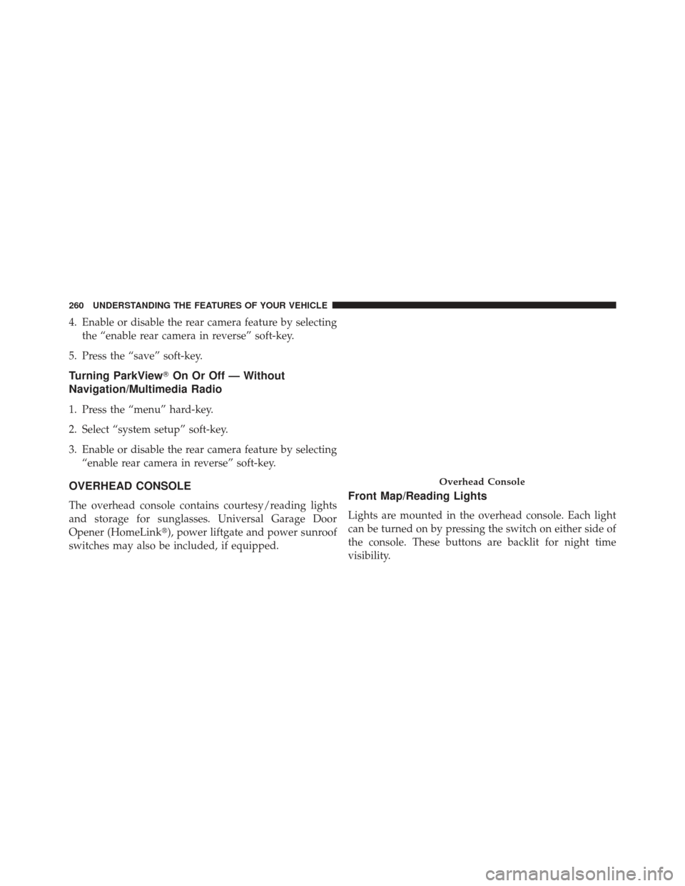
OVERHEAD CONSOLE
The overhead console contains courtesy/reading lights
and storage for sunglasses. Universal Garage Door
Opener (HomeLink�), power liftgate and power sunroof
switches may also be included, if equipped.Front Map/Reading Lights
Lights are mounted in the overhead console. Each light
can be turned on by pressing the switch on either side of
the console. These buttons are backlit for night time
visibility.
Overhead Console
260 UNDERSTANDING THE FEATURES OF YOUR VEHICLE
Page 274 of 699
. Occupants,")
WARNING!
•Never leave children in a vehicle with the key in
the ignition switch (or with the ignition in the
Accessory or Run position, for vehicles equipped
with Keyless Enter-N-Go™). Occupants, particu-
larly unattended children, can become entrapped
by the power sunroof while operating the power
sunroof switch. Such entrapment may result in
serious injury or death.
• In a collision, there is a greater risk of being thrown
from a vehicle with an open sunroof. You could
also be seriously injured or killed. Always fasten
your seat belt properly and make sure all passen-
gers are also properly secured.
• Do not allow small children to operate the sunroof.
Never allow your fingers, other body parts, or any
object, to project through the sunroof opening.
Injury may result.
Opening Sunroof — Express
Press the switch rearward and release it within one-half
second and the sunroof will open automatically from any
position. The sunroof will open fully and stop automati-
cally. This is called “Express Open”. During Express
Open operation, any movement of the sunroof switch
will stop the sunroof.
Opening Sunroof — Manual Mode
To open the sunroof, press and hold the switch rearward
to full open. Any release of the switch will stop the
movement and the sunroof will remain in a partially
opened condition until the switch is pushed and held
rearward again.
Closing Sunroof — Express
Press the switch forward and release it within one-half
second and the sunroof will close automatically from any
272 UNDERSTANDING THE FEATURES OF YOUR VEHICLE
Page 277 of 699
 power
outlets that can be used to power cellular phones, small
electronics and other low powered electrical accessories.
The pow")
ELECTRICAL POWER OUTLETS
Your vehicle is equipped with 12 Volt (13 Amp) power
outlets that can be used to power cellular phones, small
electronics and other low powered electrical accessories.
The power outlets are labeled with either a “key” or a
“battery” symbol to indicate how the outlet is powered.
Power outlets labeled with a “key” are powered when
the ignition switch is in the ON or ACC position, while
the outlets labeled with a “battery” are connected directly
to the battery and powered at all times.
NOTE:
•All accessories connected to the “battery” powered
outlets should be removed or turned off when the
vehicle is not in use to protect the battery against
discharge. •
To ensure proper operation a MOPAR� knob and
element must be used.
• Do not exceed the maximum power of 160 Watts (13
Amps) at 12 Volts. If the 160 Watt (13 Amp) power
rating is exceeded the fuse protecting the system will
need to be replaced.
• Power outlets are designed for accessory plugs only.
Do not insert any other object in the power outlets as
this will damage the outlet and blow the fuse. Im-
proper use of the power outlet can cause damage not
covered by your New Vehicle Limited Warranty.
3
UNDERSTANDING THE FEATURES OF YOUR VEHICLE 275
Page 307 of 699
UNDERSTANDING YOUR INSTRUMENT PANEL
CONTENTS
�INSTRUMENT PANEL FEATURES ..........309
� INSTRUMENT CLUSTER .................310
� INSTRUMENT CLUSTER DESCRIPTIONS .....311
� ELECTRONIC VEHICLE INFORMATION
CENTER (EVIC) ...................... .322
▫ Electronic Vehicle Information Center (EVIC)
Displays ........................... .324
▫ EVIC White Telltale Lights ...............330
▫ EVIC Amber Telltale Lights ..............332
▫ EVIC Red Telltale Lights ................332 ▫
Engine Oil Change Indicator System ........335
▫ Fuel Economy ....................... .336
▫ Vehicle Speed ....................... .338
▫ Trip Info .......................... .338
▫ Vehicle Info (Customer Information Features) . .339
▫ Units ............................. .339
▫ Keyless Enter-N-Go™ Display —
If Equipped ........................ .340
▫ Messages # ......................... .340
▫ Turn Menu OFF ...................... .340
4
Page 314 of 699

Your vehicle has also been equipped with a TPMS
malfunction indicator to indicate when the system is not
operating properly. The TPMS malfunction indicator is
combined with the low tire pressure telltale. When the
system detects a malfunction, the telltale will flash for
approximately one minute and then remain continuously
illuminated. This sequence will continue upon subse-
quent vehicle start-ups as long as the malfunction exists.
When the malfunction indicator is illuminated, the sys-
tem may not be able to detect or signal low tire pressure
as intended. TPMS malfunctions may occur for a variety
of reasons, including the installation of replacement or
alternate tires or wheels on the vehicle that prevent the
TPMS from functioning properly. Always check the
TPMS malfunction telltale after replacing one or more
tires or wheels on your vehicle, to ensure that the
replacement or alternate tires and wheels allow the TPMS
to continue to function properly.CAUTION!
The TPMS has been optimized for the original
equipment tires and wheels. TPMS pressures and
warning have been established for the tire size
equipped on your vehicle. Undesirable system opera-
tion or sensor damage may result when using re-
placement equipment that is not of the same size,
type, and/or style. Aftermarket wheels can cause
sensor damage. Do not use tire sealant from a can or
balance beads if your vehicle is equipped with a
TPMS, as damage to the sensors may result.
3. Malfunction Indicator Light (MIL) The Malfunction Indicator Light (MIL) is part of
an onboard diagnostic system called OBD II that
monitors engine and automatic transmission con-
trol systems. The light will illuminate when the key is in
the ON/RUN position before engine start. If the bulb
312 UNDERSTANDING YOUR INSTRUMENT PANEL
Page 315 of 699

does not come on when turning the key from OFF to
ON/RUN, have the condition checked promptly.
Certain conditions, such as a loose or missing gas cap,
poor fuel quality, etc., may illuminate the light after
engine start. The vehicle should be serviced if the light
stays on through several of your typical driving cycles. In
most situations, the vehicle will drive normally and will
not require towing.
CAUTION!
Prolonged driving with the MIL on could cause
damage to the engine control system. It also could
affect fuel economy and drivability. If the MIL is
flashing, severe catalytic converter damage and
power loss will soon occur. Immediate service is
required.
WARNING!
A malfunctioning catalytic converter, as referenced
above, can reach higher temperatures than in normal
operating conditions. This can cause a fire if you
drive slowly or park over flammable substances such
as dry plants, wood, cardboard, etc. This could result
in death or serious injury to the driver, occupants or
others.
4. Electronic Stability Control (ESC) Activation/
Malfunction Indicator Light — If Equipped The “ESC Activation/Malfunction Indicator
Light” in the instrument cluster will come on
when the ignition switch is turned to the
ON/RUN position. It should go out with the
engine running. If the “ESC Activation/Malfunction In-
dicator Light” comes on continuously with the engine
running, a malfunction has been detected in the ESC
4
UNDERSTANDING YOUR INSTRUMENT PANEL 313
Page 327 of 699
 and “Lights On” (if driver leaves the vehicle).
•Unstored Messages Until RUN
These messages deal primarily with the Re")
of this message type are “Turn Signal On” (if a turn signal
is left on) and “Lights On” (if driver leaves the vehicle).
•Unstored Messages Until RUN
These messages deal primarily with the Remote Start
feature. This message type is displayed until the ignition
is in the RUN state. Examples of this message type are
“Remote Start Aborted - Door Ajar” and “Press Brake
Pedal and Push Button to Start”.
• Five Second Unstored Messages
When the appropriate conditions occur, this type of
message takes control of the main display area for five
seconds and then returns to the previous screen. Ex-
amples of this message type are “Memory System Un-
available - Not in Park” and “Automatic High Beams
On”. The Reconfigurable Telltales section is divided into the
white telltales area on the right, amber telltales in the
middle, and red telltales on the left.
When the appropriate conditions exist, the EVIC displays
the following messages:
•
Vehicle Not in Park
• Key Left Vehicle
• Key Not Detected
• Press Brake Pedal and Push Button to Start
• Premium TPM System Graphic Display
• Service TPM System (refer to “Tire Pressure Monitor-
ing System” in “Starting And Operating”)
• Service Keyless System (refer to Keyless Enter-N-Go™,
Passive Entry - if equipped)
• Service Park Assist System
4
UNDERSTANDING YOUR INSTRUMENT PANEL 325