2013 BMW ACTIVEHYBRID3 wheel
[x] Cancel search: wheelPage 124 of 220
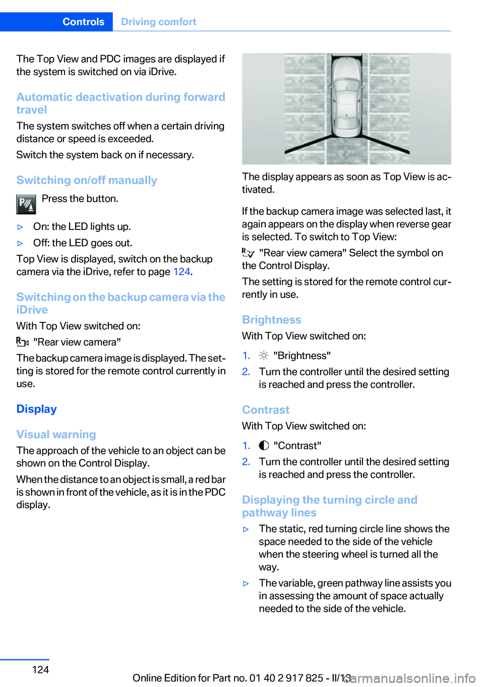
The Top View and PDC images are displayed if
the system is switched on via iDrive.
Automatic deactivation during forward
travel
The system switches off when a certain driving
distance or speed is exceeded.
Switch the system back on if necessary.
Switching on/off manually Press the button.▷On: the LED lights up.▷Off: the LED goes out.
Top View is displayed, switch on the backup
camera via the iDrive, refer to page 124.
Switching on the backup camera via the
iDrive
With Top View switched on:
"Rear view camera"
The backup camera image is displayed. The set‐
ting is stored for the remote control currently in
use.
Display
Visual warning
The approach of the vehicle to an object can be
shown on the Control Display.
When the distance to an object is small, a red bar
is shown in front of the vehicle, as it is in the PDC
display.
The display appears as soon as Top View is ac‐
tivated.
If the backup camera image was selected last, it
again appears on the display when reverse gear
is selected. To switch to Top View:
"Rear view camera" Select the symbol on
the Control Display.
The setting is stored for the remote control cur‐
rently in use.
Brightness
With Top View switched on:
1. "Brightness"2.Turn the controller until the desired setting
is reached and press the controller.
Contrast
With Top View switched on:
1. "Contrast"2.Turn the controller until the desired setting
is reached and press the controller.
Displaying the turning circle and
pathway lines
▷The static, red turning circle line shows the
space needed to the side of the vehicle
when the steering wheel is turned all the
way.▷The variable, green pathway line assists you
in assessing the amount of space actually
needed to the side of the vehicle.Seite 124ControlsDriving comfort124
Online Edition for Part no. 01 40 2 917 825 - II/13
Page 125 of 220
The pathway line is dependent on the cur‐
rent steering angle and is continuously ad‐
justed with the steering wheel movement.
"Parking aid lines"
Turning circle and pathway lines are displayed.
System limits
Top View cannot be used in the following situa‐
tions:
▷With a door open.▷With the trunk lid open.▷With an exterior mirror folded in.▷In poor light.
A Check Control message is displayed in some
of these situations.
Side View
The concept
Side View provides an early look at cross traffic
at blind driveways and intersections. Road users
concealed by obstacles to the left and right of
the vehicle can only be detected relatively late
from the driver's seat. To improve visibility, two
cameras in the front of the vehicle record the
traffic situation on each side.
Notes
The images from both cameras are shown si‐
multaneously on the Control Display.
Check the traffic situation as well
Check the traffic situation around the ve‐
hicle on blind driveways and intersections with
your own eyes. Otherwise, an accident could re‐
sult from road users or objects located outside
the picture area of the Side View cameras.◀
At a glance
Button in the vehicle
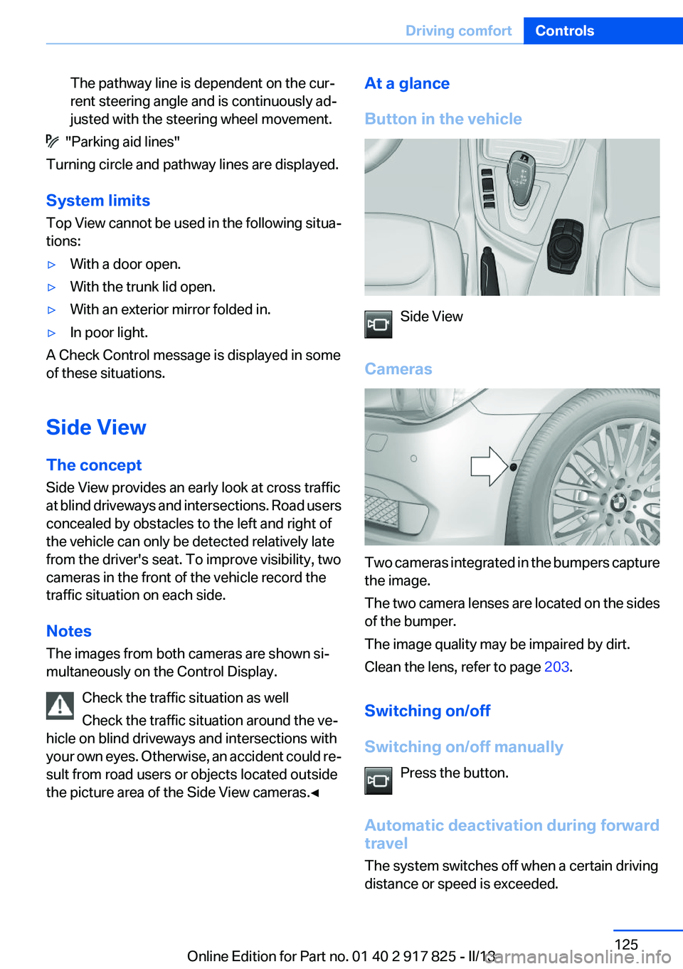
Side View
Cameras
Two cameras integrated in the bumpers capture
the image.
The two camera lenses are located on the sides
of the bumper.
The image quality may be impaired by dirt.
Clean the lens, refer to page 203.
Switching on/off
Switching on/off manually Press the button.
Automatic deactivation during forward
travel
The system switches off when a certain driving
distance or speed is exceeded.
Seite 125Driving comfortControls125
Online Edition for Part no. 01 40 2 917 825 - II/13
Page 128 of 220

A component of the parking assistant is the PDC
Park Distance Control, refer to page 118.
Notes Personal responsibility
The parking assistant does not relieve the
driver of responsibility for the vehicle during the
parking procedure.
Watch the parking space and parking procedure
closely and intervene if necessary; otherwise,
there is the danger of an accident.◀
Changes to the parking space
Changes to the parking space after it was
measured are not taken into account by the sys‐
tem.
Therefore, always be alert and ready to inter‐
vene; otherwise, there is the danger of an acci‐
dent occurring.◀
Transporting loads
Loads that extend beyond the perimeter
of the vehicle are not taken into account by the
system during the parking procedure.
Therefore, always be alert and ready to inter‐
vene; otherwise, there is the danger of an acci‐
dent occurring.◀
Curbs
The parking assistant may steer the vehi‐
cle over or onto curbs.
Therefore, always be alert and ready to inter‐
vene; otherwise, the wheels, tires, or the vehicle
may become damaged.◀
An engine that has been switched off by the
Auto Start Stop function is restarted automati‐
cally when the parking assistant is activated.
Requirements
For measuring parking spaces▷Maximum speed while driving forward ap‐
prox. 22 mph/35 km/h.▷Maximum distance to row of parked vehi‐
cles: 5 ft/1.5 m.▷When parking in parking spaces on the driv‐
er's side, the corresponding turn signal must
be set.
Suitable parking space
▷Gap between two objects with a minimum
length of approx. 5 ft/1.5 m.▷Minimum length of the gap: own vehicle's
length plus approx 4 ft/1.2 m.▷Minimum depth: approx. 5 ft/1.5 m.
For parking procedure
Closed doors.
At a glance
Button in the vehicle
Parking assistant
Ultrasound sensors
The ultrasound sensors for measuring parking
spaces are located on the wheel arches.
Seite 128ControlsDriving comfort128
Online Edition for Part no. 01 40 2 917 825 - II/13
Page 130 of 220

With Professional navigation system or
TV: system status▷Colored symbols, see arrows, on the side of
the vehicle representation. Parking assis‐
tant is activated and search for parking
space active.▷Suitable parking spaces are displayed next
to the vehicle symbol at the edge of the road
as on the Control Display. When the parking
assistant is active, suitable parking spaces
are highlighted.▷The parking procedure is ac‐
tive. Steering control has
been seized.▷Parking space search is always active when‐
ever the vehicle is moving forwards slow and
straight, even if the system is deactivated.
When the system is deactivated, the dis‐
plays on the Control Display are shown in
gray.
Parking using the parking assistant
Check the traffic situation as well
Loud sounds outside and within the vehi‐
cle can drown out the signal tones of the parking
assistant and PDC.
Check the traffic situation around the vehicle
with your own eyes; otherwise, there is the dan‐
ger of an accident.◀
1.Switch on the parking assistant and activate
it if necessary.The status of the parking space search is in‐
dicated on the Control Display.2.Follow the instructions on the Control Dis‐
play.
To achieve the best possible parking posi‐
tion, wait for the automatic steering wheel
movement after the gear change when the
vehicle is stationary.
The end of the parking procedure is indi‐
cated on the Control Display.3.Adjust the parking position yourself if nec‐
essary.
Interrupting manually
The parking assistant can be interrupted at any
time:
▷ " Parking Assistant" Select the symbol on
the Control Display.▷Press the button.
Interrupting automatically
The system is interrupted automatically in the
following situations:
▷If the driver grasps the steering wheel or if
he takes over steering.▷If a gear is selected that does not match the
instruction on the Control Display.▷If a turn signal is activated in the opposite
direction to the desired side for parking.▷If the vehicle speed exceeds approx.
6 mph/10 km/h.▷On snow-covered or slippery road surfaces
if necessary.▷If doors are open.▷If the trunk lid is open.▷If a maximum number of parking attempts or
the time taken for parking is exceeded.
A Check Control message is displayed.
Seite 130ControlsDriving comfort130
Online Edition for Part no. 01 40 2 917 825 - II/13
Page 133 of 220
Climate control functions in detail
Temperature Turn the wheel to set the desired
temperature.
The automatic climate control reaches this tem‐
perature as quickly as possible, if necessary by
increasing the cooling or heating output, and
then keeps it constant.
Avoid rapidly switching between different tem‐
perature settings. The automatic climate control
will not have sufficient time to adjust the set
temperature.
AUTO program Press the button.
Air flow, air distribution, and tempera‐
ture are controlled automatically.
Depending on the selected temperature, AUTO
intensity, and outside influences, the air is di‐
rected to the windshield, side windows, upper
body, and into the footwell.
The cooling function, refer to page 133, is
switched on automatically with the AUTO pro‐
gram.
At the same time, a condensation sensor con‐
trols the program so as to prevent window con‐
densation as much as possible.
Intensity of the AUTO program
With the AUTO program switched on, automatic
control of the air flow and air distribution can be
adjusted.
Press the left or right side of the button:
decrease or increase the intensity.
The selected intensity is shown on the display
of the automatic climate control.Maximum cooling
Press the button.
The system is set to the lowest tem‐
perature, maximum air flow and recirculated-air
mode.
Air flows out of the vents for the upper body re‐
gion. The vents need to be open for this.
The air is cooled fastest when the engine is run‐
ning.
The air flow can be adjusted when the program
is active.
Cooling function
The passenger compartment can be cooled
with the engine running or switched off.
Press the button.
The air is cooled and dehumidified and,
depending on the temperature setting, warmed
again.
Depending on the weather, the windshield may
fog up briefly when the engine is started.
The cooling function is switched on automati‐
cally with the AUTO program.
When using the automatic climate control, con‐
densation water, refer to page 155, develops
that exits underneath the vehicle.
Automatic recirculated-air control/
recirculated-air mode
You can respond to unpleasant odors or pollu‐
tants in the immediate environment by tempo‐
rarily suspending the supply of outside air. The
system then recirculates the air currently within
the vehicle.
Press the button repeatedly to select
an operating mode:▷LEDs off: outside air flows in continuously.▷Left LED on, automatic recirculated-air con‐
trol: a sensor detects pollutants in the out‐Seite 133Climate controlControls133
Online Edition for Part no. 01 40 2 917 825 - II/13
Page 135 of 220
Ventilation
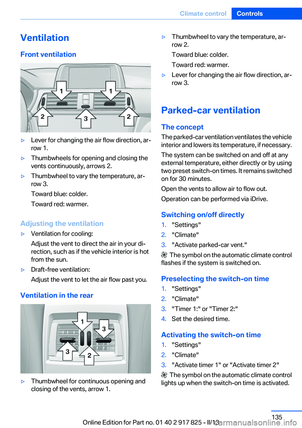
Front ventilation▷Lever for changing the air flow direction, ar‐
row 1.▷Thumbwheels for opening and closing the
vents continuously, arrows 2.▷Thumbwheel to vary the temperature, ar‐
row 3.
Toward blue: colder.
Toward red: warmer.
Adjusting the ventilation
▷Ventilation for cooling:
Adjust the vent to direct the air in your di‐
rection, such as if the vehicle interior is hot
from the sun.▷Draft-free ventilation:
Adjust the vent to let the air flow past you.
Ventilation in the rear
▷Thumbwheel for continuous opening and
closing of the vents, arrow 1.▷Thumbwheel to vary the temperature, ar‐
row 2.
Toward blue: colder.
Toward red: warmer.▷Lever for changing the air flow direction, ar‐
row 3.
Parked-car ventilation
The concept
The parked-car ventilation ventilates the vehicle
interior and lowers its temperature, if necessary.
The system can be switched on and off at any
external temperature, either directly or by using
two preset switch-on times. It remains switched
on for 30 minutes.
Open the vents to allow air to flow out.
Operation can be performed via iDrive.
Switching on/off directly
1."Settings"2."Climate"3."Activate parked-car vent."
The symbol on the automatic climate control
flashes if the system is switched on.
Preselecting the switch-on time
1."Settings"2."Climate"3."Timer 1:" or "Timer 2:"4.Set the desired time.
Activating the switch-on time
1."Settings"2."Climate"3."Activate timer 1" or "Activate timer 2"
The symbol on the automatic climate control
lights up when the switch-on time is activated.
Seite 135Climate controlControls135
Online Edition for Part no. 01 40 2 917 825 - II/13
Page 165 of 220
Mobility
To ensure that you remain mobile at all times, this chapter supplies you with important information
on the topics of fuels and lubricants, wheels and tires, service, maintenance, and Roadside Assistance.Online Edition for Part no. 01 40 2 917 825 - II/13
Page 169 of 220
Wheels and tiresVehicle equipment
All standard, country-specific and optional
equipment that is offered in the model series is
described in this chapter. Therefore, equipment
is also described that is not available in a vehicle,
e. g., because of the selected optional equip‐
ment or country variant. This also applies for
safety-related functions and systems.
Tire inflation pressure
Safety information
The tire characteristics and tire inflation pres‐
sure influence the following:▷The service life of the tires.▷Road safety.▷Driving comfort.
Checking the pressure
Only check the tire inflation pressure when the
tires are cold. This means after driving no more
than 1.25 miles/2 km or when the vehicle has
been parked for at least 2 hours. When the tires
are warm, the tire inflation pressure is higher.
Check the tire inflation pressure regularly
Regularly check the tire inflation pressure
and correct it as needed: at least twice a month
and before a long trip. If you fail to observe this
precaution, you may be driving on tires with in‐
correct tire pressures, a condition that may not
only compromise your vehicle's driving stability,
but also lead to tire damage and the risk of an
accident.◀
After correcting the tire inflation pressure:
▷Reinitialize the Flat Tire Monitor.▷Reinitialize the Tire Pressure Monitor.Pressure specifications
The tire inflation pressure table, refer to
page 170, contains all pressure specifications
for the specified tire sizes at the ambient tem‐
perature. Pressure specifications apply to ap‐
proved tire sizes and recommended tire brands.
This information can be obtained from your
service center.
To identify the correct tire inflation pressure,
please note the following:▷Tire sizes of your vehicle.▷Maximum permitted driving speed.
Tire inflation pressures up to 100 mph/
160 km/h
For speeds of up to 100 mph/160 km/h and for
optimum driving comfort, note the pressure val‐
ues in the tire inflation pressure table, refer to
page 170, and adjust as necessary.
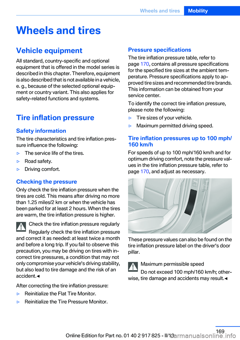
These pressure values can also be found on the
tire inflation pressure label on the driver's door
pillar.
Maximum permissible speed
Do not exceed 100 mph/160 km/h; other‐
wise, tire damage and accidents may result.◀
Seite 169Wheels and tiresMobility169
Online Edition for Part no. 01 40 2 917 825 - II/13