2013 BMW ACTIVEHYBRID3 display
[x] Cancel search: displayPage 83 of 220
▷Where there are railroad crossings, highway
markings or other situations where no sig‐
nage is present, but passing would not be
permitted.
Hints
Speed limits when towing a trailer are not
shown.
Personal judgment
The system cannot serve as a substitute
for the driver's personal judgment of the traffic
situation.
The system assists the driver and does not re‐
place the human eye.◀
At a glance
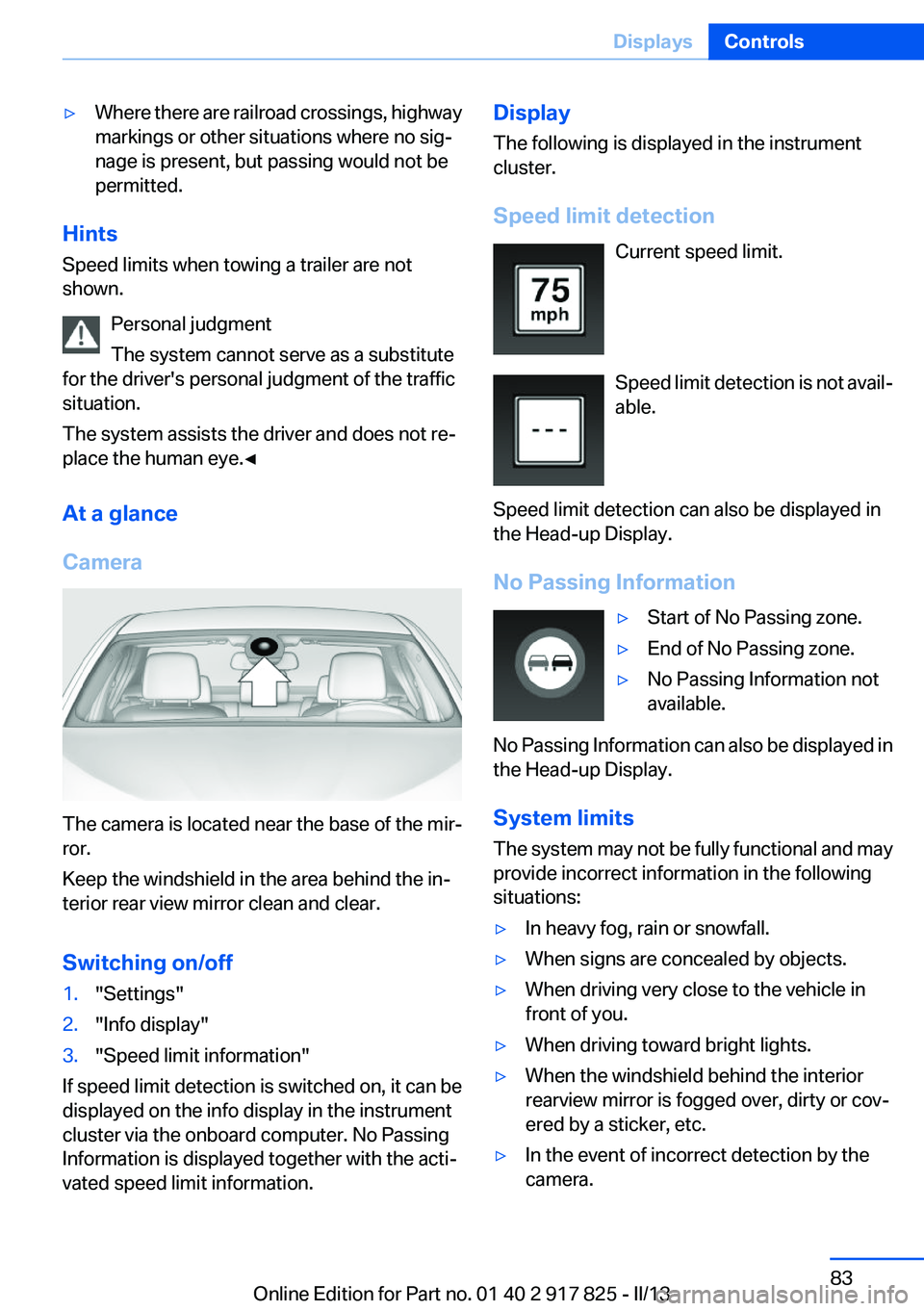
Camera
The camera is located near the base of the mir‐
ror.
Keep the windshield in the area behind the in‐
terior rear view mirror clean and clear.
Switching on/off
1."Settings"2."Info display"3."Speed limit information"
If speed limit detection is switched on, it can be
displayed on the info display in the instrument
cluster via the onboard computer. No Passing
Information is displayed together with the acti‐
vated speed limit information.
Display
The following is displayed in the instrument
cluster.
Speed limit detection Current speed limit.
Speed limit detection is not avail‐
able.
Speed limit detection can also be displayed in
the Head-up Display.
No Passing Information▷Start of No Passing zone.▷End of No Passing zone.▷No Passing Information not
available.
No Passing Information can also be displayed in
the Head-up Display.
System limits
The system may not be fully functional and may
provide incorrect information in the following
situations:
▷In heavy fog, rain or snowfall.▷When signs are concealed by objects.▷When driving very close to the vehicle in
front of you.▷When driving toward bright lights.▷When the windshield behind the interior
rearview mirror is fogged over, dirty or cov‐
ered by a sticker, etc.▷In the event of incorrect detection by the
camera.Seite 83DisplaysControls83
Online Edition for Part no. 01 40 2 917 825 - II/13
Page 84 of 220
▷If the speed limits stored in the navigation
system are incorrect.▷In areas not covered by the navigation sys‐
tem.▷When roads differ from the navigation, such
as due to changes in the road network.▷When passing buses or trucks with a speed
sticker.▷If the traffic signs are non-conforming.▷During calibration of the camera immedi‐
ately after vehicle shipment.
Selection lists in the
instrument cluster
The concept
The following can be displayed or operated us‐
ing the buttons and the thumbwheel on the
steering wheel and the display in the instrument
cluster:
▷Current audio source.▷Redial on telephone.▷Activation of the voice activation system.
In addition, programs of the Driving Dynamics
Control are displayed.
Display
Instrument cluster with enhanced
features
Activating a list and adjusting the
setting
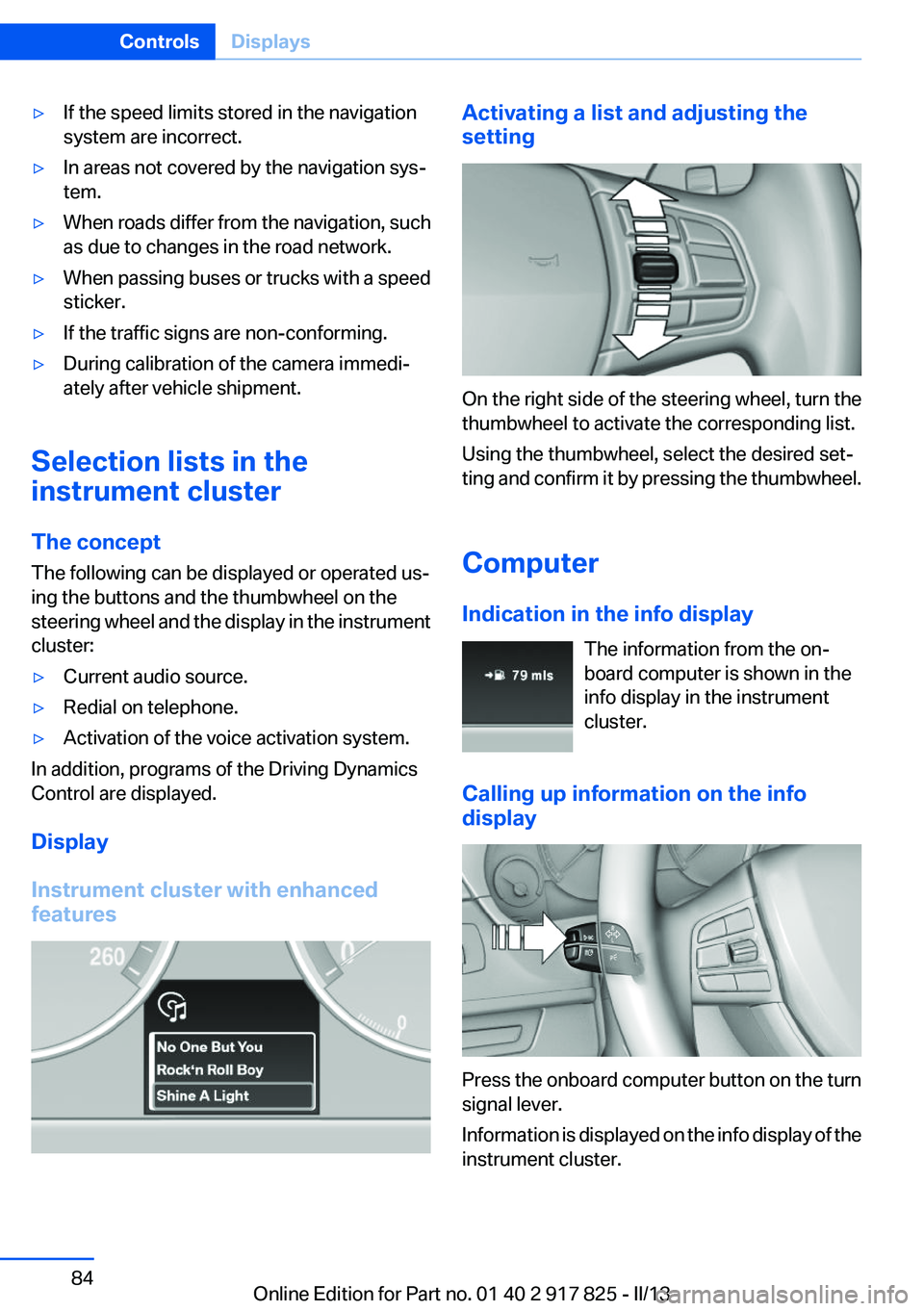
On the right side of the steering wheel, turn the
thumbwheel to activate the corresponding list.
Using the thumbwheel, select the desired set‐
ting and confirm it by pressing the thumbwheel.
Computer
Indication in the info display The information from the on‐
board computer is shown in the
info display in the instrument
cluster.
Calling up information on the info
display
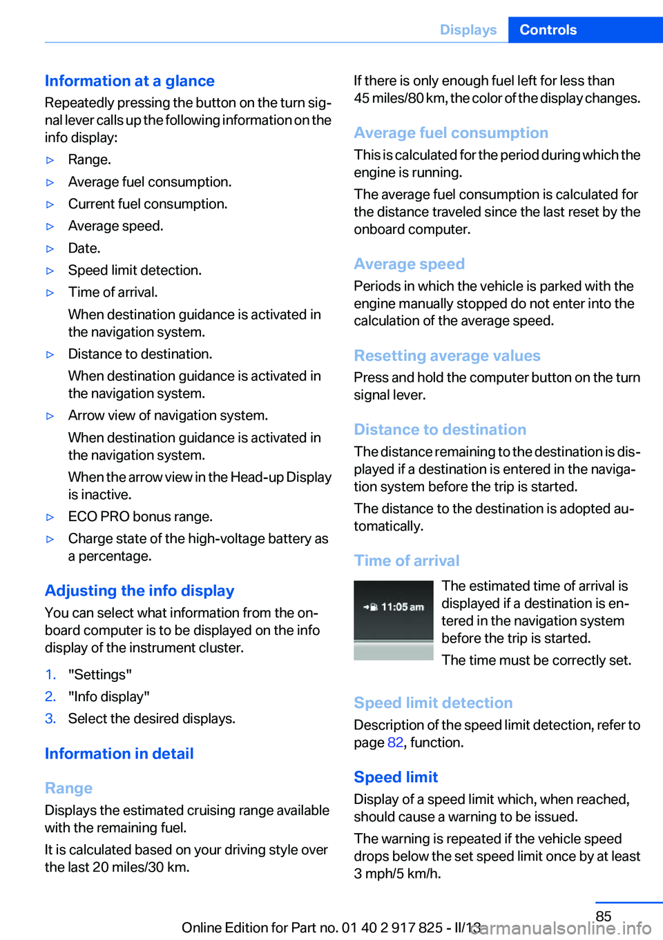
Press the onboard computer button on the turn
signal lever.
Information is displayed on the info display of the
instrument cluster.
Seite 84ControlsDisplays84
Online Edition for Part no. 01 40 2 917 825 - II/13
Page 85 of 220
Information at a glance
Repeatedly pressing the button on the turn sig‐
nal lever calls up the following information on the
info display:▷Range.▷Average fuel consumption.▷Current fuel consumption.▷Average speed.▷Date.▷Speed limit detection.▷Time of arrival.
When destination guidance is activated in
the navigation system.▷Distance to destination.
When destination guidance is activated in
the navigation system.▷Arrow view of navigation system.
When destination guidance is activated in
the navigation system.
When the arrow view in the Head-up Display
is inactive.▷ECO PRO bonus range.▷Charge state of the high-voltage battery as
a percentage.
Adjusting the info display
You can select what information from the on‐
board computer is to be displayed on the info
display of the instrument cluster.
1."Settings"2."Info display"3.Select the desired displays.
Information in detail
Range
Displays the estimated cruising range available
with the remaining fuel.
It is calculated based on your driving style over
the last 20 miles/30 km.
If there is only enough fuel left for less than
45 miles/80 km, the color of the display changes.
Average fuel consumption
This is calculated for the period during which the
engine is running.
The average fuel consumption is calculated for
the distance traveled since the last reset by the
onboard computer.
Average speed
Periods in which the vehicle is parked with the
engine manually stopped do not enter into the
calculation of the average speed.
Resetting average values
Press and hold the computer button on the turn
signal lever.
Distance to destination
The distance remaining to the destination is dis‐
played if a destination is entered in the naviga‐
tion system before the trip is started.
The distance to the destination is adopted au‐
tomatically.
Time of arrival The estimated time of arrival is
displayed if a destination is en‐
tered in the navigation system
before the trip is started.
The time must be correctly set.
Speed limit detection
Description of the speed limit detection, refer to
page 82, function.
Speed limit
Display of a speed limit which, when reached,
should cause a warning to be issued.
The warning is repeated if the vehicle speed
drops below the set speed limit once by at least
3 mph/5 km/h.Seite 85DisplaysControls85
Online Edition for Part no. 01 40 2 917 825 - II/13
Page 86 of 220
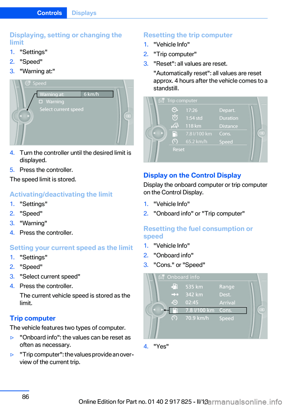
Displaying, setting or changing the
limit1."Settings"2."Speed"3."Warning at:"4.Turn the controller until the desired limit is
displayed.5.Press the controller.
The speed limit is stored.
Activating/deactivating the limit
1."Settings"2."Speed"3."Warning"4.Press the controller.
Setting your current speed as the limit
1."Settings"2."Speed"3."Select current speed"4.Press the controller.
The current vehicle speed is stored as the
limit.
Trip computer
The vehicle features two types of computer.
▷"Onboard info": the values can be reset as
often as necessary.▷" Trip computer": the values provide an over‐
view of the current trip.Resetting the trip computer1."Vehicle Info"2."Trip computer"3."Reset": all values are reset.
"Automatically reset": all values are reset
approx. 4 hours after the vehicle comes to a
standstill.
Display on the Control Display
Display the onboard computer or trip computer
on the Control Display.
1."Vehicle Info"2."Onboard info" or "Trip computer"
Resetting the fuel consumption or
speed
1."Vehicle Info"2."Onboard info"3."Cons." or "Speed"4."Yes"Seite 86ControlsDisplays86
Online Edition for Part no. 01 40 2 917 825 - II/13
Page 87 of 220
Sport displays
In the Control Display, the current system values
of hybrid operation for power and torque can be
displayed.
Displaying sport displays in the Control
Display1."Vehicle Info"2."Sport displays"
Settings on the Control
Display
Time
Setting the time zone
1."Settings"2."Time/Date"3."Time zone"4.Select the desired time zone.
The time zone is stored.
Setting the time
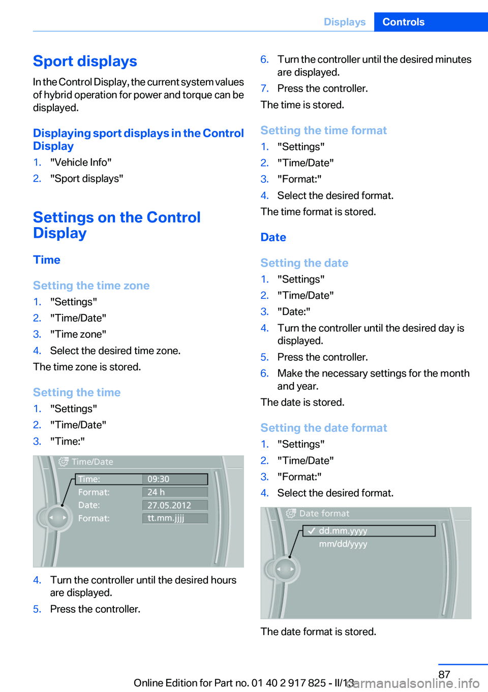
1."Settings"2."Time/Date"3."Time:"4.Turn the controller until the desired hours
are displayed.5.Press the controller.6.Turn the controller until the desired minutes
are displayed.7.Press the controller.
The time is stored.
Setting the time format
1."Settings"2."Time/Date"3."Format:"4.Select the desired format.
The time format is stored.
Date
Setting the date
1."Settings"2."Time/Date"3."Date:"4.Turn the controller until the desired day is
displayed.5.Press the controller.6.Make the necessary settings for the month
and year.
The date is stored.
Setting the date format
1."Settings"2."Time/Date"3."Format:"4.Select the desired format.
The date format is stored.
Seite 87DisplaysControls87
Online Edition for Part no. 01 40 2 917 825 - II/13
Page 88 of 220
Language
Setting the language
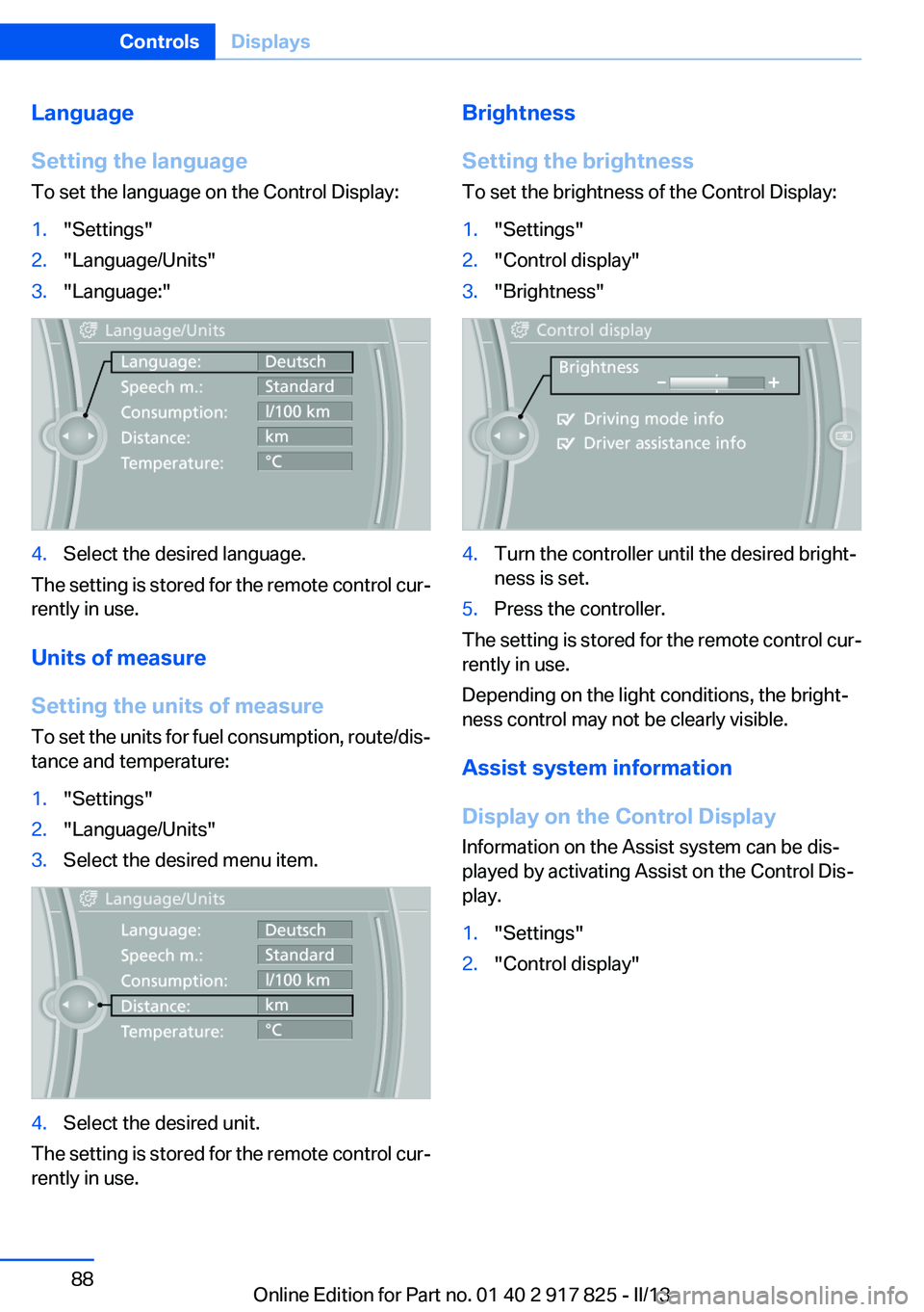
To set the language on the Control Display:1."Settings"2."Language/Units"3."Language:"4.Select the desired language.
The setting is stored for the remote control cur‐
rently in use.
Units of measure
Setting the units of measure
To set the units for fuel consumption, route/dis‐
tance and temperature:
1."Settings"2."Language/Units"3.Select the desired menu item.4.Select the desired unit.
The setting is stored for the remote control cur‐
rently in use.
Brightness
Setting the brightness
To set the brightness of the Control Display:1."Settings"2."Control display"3."Brightness"4.Turn the controller until the desired bright‐
ness is set.5.Press the controller.
The setting is stored for the remote control cur‐
rently in use.
Depending on the light conditions, the bright‐
ness control may not be clearly visible.
Assist system information
Display on the Control Display
Information on the Assist system can be dis‐
played by activating Assist on the Control Dis‐
play.
1."Settings"2."Control display"Seite 88ControlsDisplays88
Online Edition for Part no. 01 40 2 917 825 - II/13
Page 89 of 220
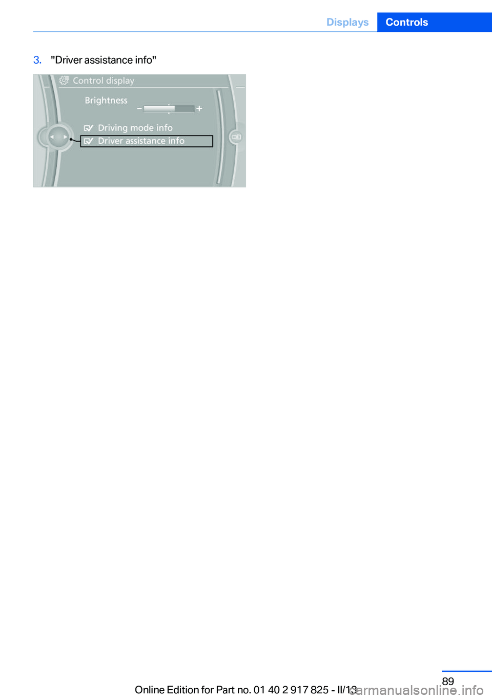
3."Driver assistance info"Seite 89DisplaysControls89
Online Edition for Part no. 01 40 2 917 825 - II/13
Page 92 of 220

Switching off
Briefly press the lever to the resistance point in
the opposite direction.
Adaptive light control
The concept
Adaptive Light Control is a variable headlamp
control system that enables dynamic illumina‐
tion of the road surface.
Depending on the steering angle and other pa‐
rameters, the light from the headlamp follows
the course of the road.
In tight curves, e.g., on mountainous roads or
when turning, one of the two front fog lamps is
switched on as a turning lamp. As a result the
inside of the curve is better lighted.
Activating
Switch position
with the ignition switched
on.
The turning lamps are automatically switched
on depending on the steering angle or the use
of turn signals.
To avoid blinding oncoming traffic, the Adaptive
Light Control does not swivel to the driver's side
when the vehicle is at a standstill.
When driving in reverse, only the turning lamp is
active.
Malfunction
A Check Control message is displayed.
Adaptive light control is malfunctioning or has
failed. Have the system checked as soon as pos‐
sible.
High-beam Assistant
The concept
When the low beams are switched on, this sys‐
tem automatically switches the high beams on
and off or suppresses the light in the areas that
blind oncoming traffic. The procedure is con‐
trolled by a sensor on the front of the interior
rearview mirror. The assistant ensures that the
high beams are switched on whenever the traffic
situation allows. The driver can intervene at any
time and switch the high beams on and off as
usual.
Activating
The High-beam Assistant can be activated
when the low beams are switched on.
1.Turn the light switch to or .2.Press the button on the turn signal lever, ar‐
row.
The indicator lamp in the instrument
cluster lights up.
When the low beams are on, the lights are au‐
tomatically brightened or dimmed.
The system responds to light from oncoming
traffic and traffic driving ahead of you, and to ad‐
equate illumination, e.g., in towns and cities.
The blue indicator lamp in the instru‐
ment cluster lights up when the system
switches on the high beams. Depending
on the version of the system in the vehicle, the
high beams may not switch off for oncoming ve‐
hicles, but may only be dimmed in the areas that
blind oncoming traffic. In this case, the blue in‐
dicator light will stay on.
Seite 92ControlsLamps92
Online Edition for Part no. 01 40 2 917 825 - II/13