2013 BMW ACTIVEHYBRID3 display
[x] Cancel search: displayPage 75 of 220

Electronic displays
Overview, instrument cluster with enhanced features1Time 78
External temperature 78
Date 78
Selection list, such as for the radio 84
Speed limit detection 82
Computer 84
Miles/trip miles 78Navigation display, see user's manual for
Navigation, Entertainment and Communi‐
cation.2Transmission display 73
ECO PRO 160
Hybrid displays 793Messages, e.g., Check Control 75
Service requirements 81Check Control
The concept
The Check Control system monitors functions
in the vehicle and notifies you of malfunctions in
the monitored systems.
A Check Control message is displayed as a
combination of indicator or warning lamps and
text messages in the instrument cluster and in
the Head-up Display.In addition, an acoustic signal may be output and
a text message may appear on the Control Dis‐
play.Seite 75DisplaysControls75
Online Edition for Part no. 01 40 2 917 825 - II/13
Page 76 of 220

Indicator/warning lamps
The indicator and warning lamps can light up in
a variety of combinations and colors.
Several of the lamps are checked for proper
functioning and light up temporarily when the
engine is started or the ignition is switched on.
Overview: indicator/warning lamps
SymbolFunction or systemTurn signalFront fog lampsRear fog lampHigh beamsHigh-beam AssistantParking lamps, headlamp controlCollision warningAdjustable speed limitSymbolFunction or systemCruise controlLane departure warningDSC Dynamic Stability ControlDSC Dynamic Stability Control is de‐
activated or DTC Dynamic Traction
Control is activatedTire Pressure Monitor
Flat Tire MonitorSafety beltsAirbag systemSteering systemEngine functionsParking brake
Brake systemIn Canadian models
Parking brake
Brake systemABS Antilock Brake SystemABS Antilock Brake System in Cana‐
dian modelsAt least one Check Control message
is displayed or is stored (symbol in
display)Seite 76ControlsDisplays76
Online Edition for Part no. 01 40 2 917 825 - II/13
Page 77 of 220

Text messages
Text messages in combination with a symbol in
the instrument cluster explain a Check Control
message and the meaning of the indicator and
warning lamps.
Supplementary text messages
Addition information, such as on the cause of a
fault or the required action, can be called up via
Check Control.
The supplementary text of urgent messages is
displayed on the Control Display automatically.
Symbols
Depending on the Check Control message, the
following functions can be selected.▷ "Owner's Manual"
Display additional information about the
Check Control message in the Integrated
Owner's Manual.▷ "Service request"
Contact the service partner.▷ "Roadside Assistance"
Contact Roadside Assistance.
Hiding Check Control messages
Press the computer button on the turn signal
lever.
▷Some Check Control messages are dis‐
played continuously and are not cleared un‐
til the malfunction is eliminated. If several
malfunctions occur at once, the messages
are displayed consecutively.These messages can be hidden for approx.
8 seconds. After this time, they are dis‐
played again automatically.▷Other Check Control messages are hidden
automatically after approx. 20 seconds.
They are stored and can be displayed again
later.
Displaying stored Check Control
messages
1."Vehicle Info"2."Vehicle status"3. "Check Control"4.Select the text message.
Messages after trip completion
Special messages that are displayed during
driving are displayed again after the ignition is
switched off.
Fuel gauge The vehicle inclination may
cause the display to vary.
US models: the arrow beside the
fuel pump symbol shows which
side of the vehicle the fuel filler
flap is on.
Hints on refueling, refer to page 166.
Tachometer
Always avoid engine speeds in the red warning
field. In this range, the fuel supply is interrupted
to protect the engine.
Seite 77DisplaysControls77
Online Edition for Part no. 01 40 2 917 825 - II/13
Page 78 of 220

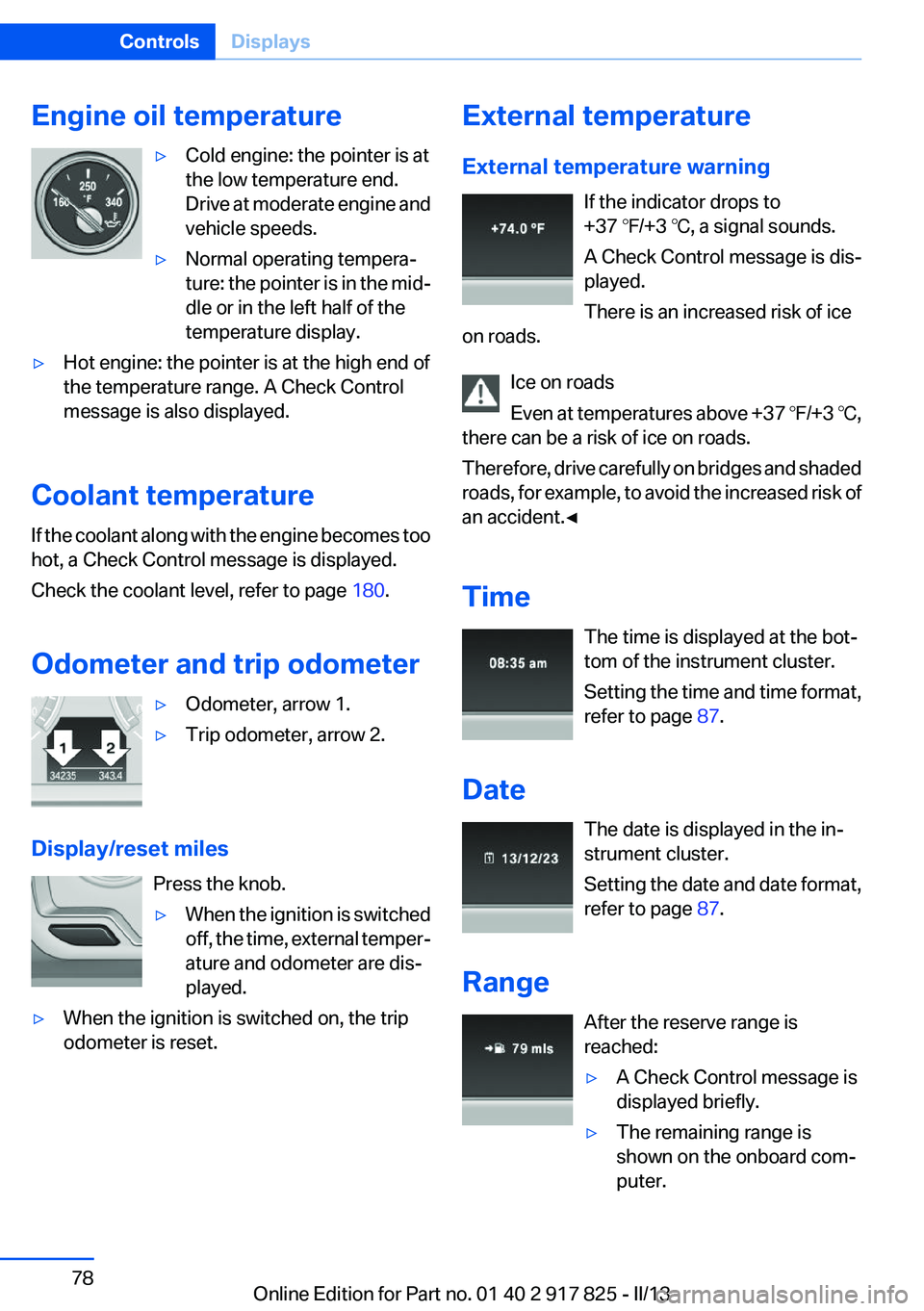
Engine oil temperature▷Cold engine: the pointer is at
the low temperature end.
Drive at moderate engine and
vehicle speeds.▷Normal operating tempera‐
ture: the pointer is in the mid‐
dle or in the left half of the
temperature display.▷Hot engine: the pointer is at the high end of
the temperature range. A Check Control
message is also displayed.
Coolant temperature
If the coolant along with the engine becomes too
hot, a Check Control message is displayed.
Check the coolant level, refer to page 180.
Odometer and trip odometer
▷Odometer, arrow 1.▷Trip odometer, arrow 2.
Display/reset miles Press the knob.
▷When the ignition is switched
off, the time, external temper‐
ature and odometer are dis‐
played.▷When the ignition is switched on, the trip
odometer is reset.External temperature
External temperature warning If the indicator drops to
+37 ℉/+3 ℃, a signal sounds.
A Check Control message is dis‐
played.
There is an increased risk of ice
on roads.
Ice on roads
Even at temperatures above +37 ℉/+3 ℃,
there can be a risk of ice on roads.
Therefore, drive carefully on bridges and shaded
roads, for example, to avoid the increased risk of
an accident.◀
Time The time is displayed at the bot‐
tom of the instrument cluster.
Setting the time and time format,
refer to page 87.
Date The date is displayed in the in‐
strument cluster.
Setting the date and date format,
refer to page 87.
Range After the reserve range is
reached:▷A Check Control message is
displayed briefly.▷The remaining range is
shown on the onboard com‐
puter.Seite 78ControlsDisplays78
Online Edition for Part no. 01 40 2 917 825 - II/13
Page 79 of 220

▷When a dynamic driving style is used, such
as when cornering quickly, operation of the
engine is not always ensured.
The Check Control message appears continu‐
ously below a range of approx. 30 miles/50 km.
Refuel promptly
Refuel no later than at a range of
30 miles/50 km, or operation of the engine is not
ensured and damage may occur.◀
Displaying the cruising range
1."Settings"2."Info display"3."Additional indicators"
The range is displayed in the instrument cluster.
Displays of the hybrid system
Displays in the instrument cluster
The concept
The display depends on the system's operating
condition. The following functions of the hybrid
system are shown in the instrument cluster.
▷High-voltage battery charge indicator.▷Electric driving: eDRIVE.▷Acceleration boost: ASSIST and eBOOST.▷Energy recovery: CHARGE.▷Auto Start/Stop function: READY.High-voltage battery charge indicator
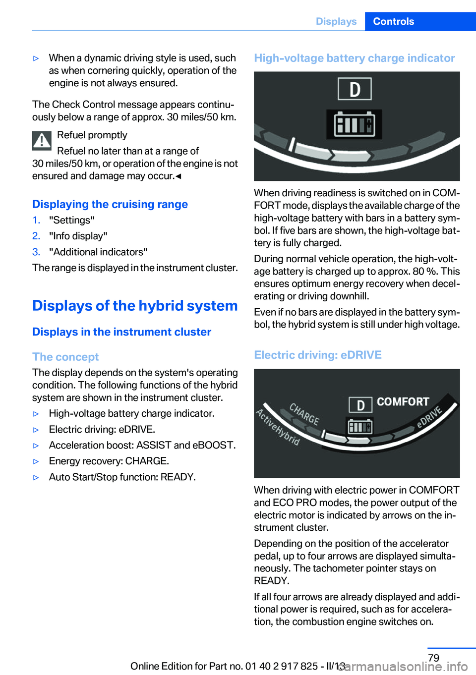
When driving readiness is switched on in COM‐
FORT mode, displays the available charge of the
high-voltage battery with bars in a battery sym‐
bol. If five bars are shown, the high-voltage bat‐
tery is fully charged.
During normal vehicle operation, the high-volt‐
age battery is charged up to approx. 80 %. This
ensures optimum energy recovery when decel‐
erating or driving downhill.
Even if no bars are displayed in the battery sym‐
bol, the hybrid system is still under high voltage.
Electric driving: eDRIVE
When driving with electric power in COMFORT
and ECO PRO modes, the power output of the
electric motor is indicated by arrows on the in‐
strument cluster.
Depending on the position of the accelerator
pedal, up to four arrows are displayed simulta‐
neously. The tachometer pointer stays on
READY.
If all four arrows are already displayed and addi‐
tional power is required, such as for accelera‐
tion, the combustion engine switches on.
Seite 79DisplaysControls79
Online Edition for Part no. 01 40 2 917 825 - II/13
Page 80 of 220

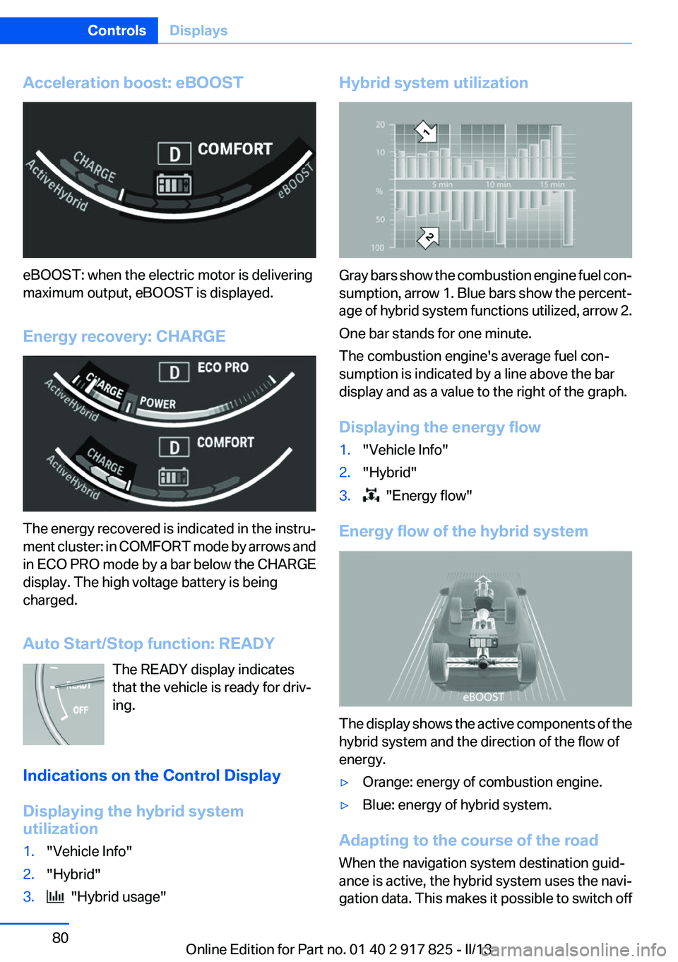
Acceleration boost: eBOOST
eBOOST: when the electric motor is delivering
maximum output, eBOOST is displayed.
Energy recovery: CHARGE
The energy recovered is indicated in the instru‐
ment cluster: in COMFORT mode by arrows and
in ECO PRO mode by a bar below the CHARGE
display. The high voltage battery is being
charged.
Auto Start/Stop function: READY The READY display indicates
that the vehicle is ready for driv‐
ing.
Indications on the Control Display
Displaying the hybrid system
utilization
1."Vehicle Info"2."Hybrid"3. "Hybrid usage"Hybrid system utilization
Gray bars show the combustion engine fuel con‐
sumption, arrow 1. Blue bars show the percent‐
age of hybrid system functions utilized, arrow 2.
One bar stands for one minute.
The combustion engine's average fuel con‐
sumption is indicated by a line above the bar
display and as a value to the right of the graph.
Displaying the energy flow
1."Vehicle Info"2."Hybrid"3. "Energy flow"
Energy flow of the hybrid system
The display shows the active components of the
hybrid system and the direction of the flow of
energy.
▷Orange: energy of combustion engine.▷Blue: energy of hybrid system.
Adapting to the course of the road
When the navigation system destination guid‐
ance is active, the hybrid system uses the navi‐
gation data. This makes it possible to switch off
Seite 80ControlsDisplays80
Online Edition for Part no. 01 40 2 917 825 - II/13
Page 81 of 220

the combustion engine upon reaching the des‐
tination zone even before reaching the destina‐
tion. The vehicle is powered only by the electric
motor.
The symbol indicates that the vehicle will
switch off the combustion engine when it enters
the destination zone.
Current fuel consumption
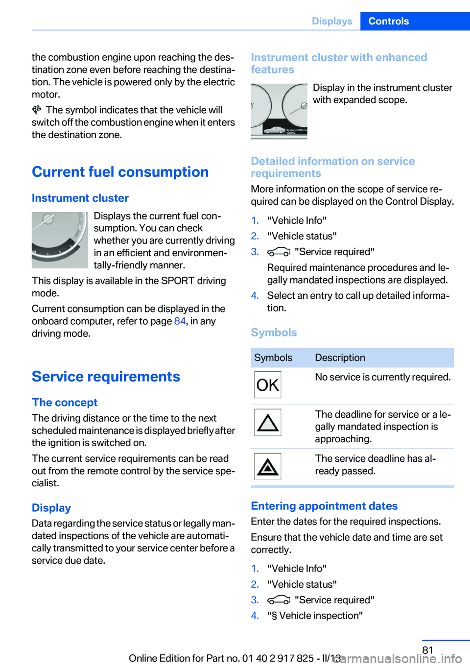
Instrument cluster Displays the current fuel con‐
sumption. You can check
whether you are currently driving
in an efficient and environmen‐
tally-friendly manner.
This display is available in the SPORT driving
mode.
Current consumption can be displayed in the
onboard computer, refer to page 84, in any
driving mode.
Service requirements
The concept
The driving distance or the time to the next
scheduled maintenance is displayed briefly after
the ignition is switched on.
The current service requirements can be read
out from the remote control by the service spe‐
cialist.
Display
Data regarding the service status or legally man‐
dated inspections of the vehicle are automati‐
cally transmitted to your service center before a
service due date.
Instrument cluster with enhanced
features
Display in the instrument cluster
with expanded scope.
Detailed information on service
requirements
More information on the scope of service re‐
quired can be displayed on the Control Display.1."Vehicle Info"2."Vehicle status"3. "Service required"
Required maintenance procedures and le‐
gally mandated inspections are displayed.4.Select an entry to call up detailed informa‐
tion.
Symbols
SymbolsDescriptionNo service is currently required.The deadline for service or a le‐
gally mandated inspection is
approaching.The service deadline has al‐
ready passed.
Entering appointment dates
Enter the dates for the required inspections.
Ensure that the vehicle date and time are set
correctly.
1."Vehicle Info"2."Vehicle status"3. "Service required"4."§ Vehicle inspection"Seite 81DisplaysControls81
Online Edition for Part no. 01 40 2 917 825 - II/13
Page 82 of 220

5."Date:"6.Adjust the settings.7.Confirm.
The entered date is stored.
Automatic Service Request
Data regarding the service status or legally man‐
dated inspections of the vehicle are automati‐
cally transmitted to your service center before a
service due date.
You can check when your service center was
notified.
1."Vehicle Info"2."Vehicle status"3.Open "Options".4."Last Service Request"
Service history
Perform maintenance work at the service center
and have them recorded in the vehicle data. The
entries are like a service booklet of the docu‐
mentation of regular maintenance.
The entered maintenance work can be dis‐
played on the Control Display. Function is avail‐
able as soon as a maintenance operation has
been entered in the vehicle data.
1."Vehicle Info"2."Vehicle status"3. "Service required"4. "Service history"
Performed maintenance operations are dis‐
played.5.Select an entry to call up detailed informa‐
tion.SymbolsSymbolsDescriptionGreen: maintenance was per‐
formed on schedule.Yellow: maintenance was per‐
formed late.Maintenance was not per‐
formed.
Speed limit detection with No
Passing Information
The concept
Speed limit detection
Speed limit detection uses a symbol in the
shape of a traffic sign to display the currently
detected speed limit. The camera at the base of
the interior rearview mirror detects traffic signs
at the edge of the road as well as variable over‐
head sign posts. Traffic signs with extra symbols
for wet road conditions, etc. are also detected
and compared with vehicle interior data, such as
for the rain sensor, and are displayed depending
on the situation. The system takes into account
the information stored in the navigation system
and also displays speed limits present on routes
without signs.
No Passing Information
No Passing Information in the instrument cluster
displays the beginnings and ends of no passing
zones detected by the camera. The system ac‐
counts for only the beginnings and ends of No
Passing zones marked by signs.
No display is shown:
▷In countries where No Passing zones are
primarily identified with road markings.▷On routes without signage.Seite 82ControlsDisplays82
Online Edition for Part no. 01 40 2 917 825 - II/13