2013 BMW ACTIVEHYBRID3 sport mode
[x] Cancel search: sport modePage 45 of 220

Panic mode
You can trigger the alarm system if you find
yourself in a dangerous situation.
Press the button on the remote control
for at least 3 seconds.
To switch off the alarm: press any button.
Switching off the alarm▷Unlock the vehicle using the remote control.▷With Comfort Access: If you are carrying the
remote control with you, pull on the driver
side or front passenger side door handle.
Indicator lamp on the interior rear view
mirror
▷The indicator lamp flashes briefly every
2 seconds:
The system is armed.▷The indicator lamp flashes after locking:
The doors, hood or trunk lid is not closed
properly, but the rest of the vehicle is se‐
cured.
After 10 seconds, the indicator lamp flashes
continuously. Interior motion sensor and tilt
alarm sensor are not active.▷The indicator lamp goes out after unlocking:
The vehicle has not been tampered with.▷The indicator lamp flashes after unlocking
until the engine ignition is switched on, but
no longer than approx. 5 minutes:
An alarm has been triggered.Tilt alarm sensor
The tilt of the vehicle is monitored.
The alarm system responds in situations such
as attempts to steal a wheel or when the car is
towed.
Interior motion sensor
The windows and glass sunroof must be closed
for the system to function properly.
Avoiding unintentional alarms
The tilt alarm sensor and interior motion sensor
can be switched off together, such as in the fol‐
lowing situations:▷In automatic car washes.▷In duplex garages.▷During transport on car-carrying trains, at
sea or on a trailer.▷When animals are to remain in the vehicle.
Switching off the tilt alarm sensor and
interior motion sensor
Press the remote control button again
within 10 seconds as soon as the vehicle
is locked.
The indicator lamp lights up for approx. 2 sec‐
onds and then continues to flash.
The tilt alarm sensor and interior motion sensor
are switched off until the vehicle is locked again.
Power windows
General information Take the remote control with you
Take the remote control with you when
leaving the vehicle so that children, for example,
cannot operate the power windows and injure
themselves.◀
Seite 45Opening and closingControls45
Online Edition for Part no. 01 40 2 917 825 - II/13
Page 59 of 220
Transporting children safelyVehicle equipment
All standard, country-specific and optional
equipment that is offered in the model series is
described in this chapter. Therefore, equipment
is also described that is not available in a vehicle,
e. g., because of the selected optional equip‐
ment or country variant. This also applies for
safety-related functions and systems.
The right place for children
Note Children in the vehicle
Do not leave children unattended in the
vehicle; otherwise, they could endanger them‐
selves and other persons, e.g., by opening the
doors.◀
Children should always be in the rear
Accident research shows that the safest place
for children is in the back seat.
Transporting children in the rear
Only transport children younger than
13 years of age or shorter than 5 ft/150 cm in the
rear in child restraint fixing systems provided in
accordance with the age, weight and size of the
child; otherwise, there is an increased risk of in‐
jury in an accident.
Children 13 years of age or older must wear a
safety belt as soon as a suitable child restraint
fixing system can no longer be used, due to their
age, weight and size.◀
Children on the front passenger seat
Should it ever be necessary to use a child re‐
straint fixing system in the front passenger seat,
make sure that the front, knee and side airbags
on the front passenger side are deactivated. Au‐tomatic deactivation of front passenger airbags,
refer to page 97.
Note Deactivated front passenger airbags
If a child restraint fixing system is used in
the front passenger seat, the front passenger
airbags must be deactivated; otherwise, there is
an increased risk of injury to the child when the
airbags are triggered, even with a child restraint
fixing system.◀
Installing child restraint fixing
systems
Before mounting
Before mounting child restraint fixing systems,
ensure that the rear seat backrests are locked.
Notes Manufacturer's information for child re‐
straint fixing systems
To select, mount and use child restraint fixing
systems, observe the information provided by
the system manufacturer; otherwise, the pro‐
tective effect can be impaired.◀
On the front passenger seat
Deactivating airbags
After installing a child restraint fixing system in
the front passenger seat, make sure that the
front, knee and side airbags on the front pas‐
senger side are deactivated.
Deactivate the front passenger airbags auto‐
matically, refer to page 97Seite 59Transporting children safelyControls59
Online Edition for Part no. 01 40 2 917 825 - II/13
Page 72 of 220
Engaging the transmission position▷Transmission position P can only be disen‐
gaged if the engine is running and the brake
pedal is pressed.▷With the vehicle stationary, press on the
brake pedal before shifting out of P or N;
otherwise, the shift command will not be
executed: shift lock.
Depress the brake until you start driv‐
ing
To prevent the vehicle from creeping after
you select a driving position, maintain pres‐
sure on the brake pedal until you are ready
to start.◀
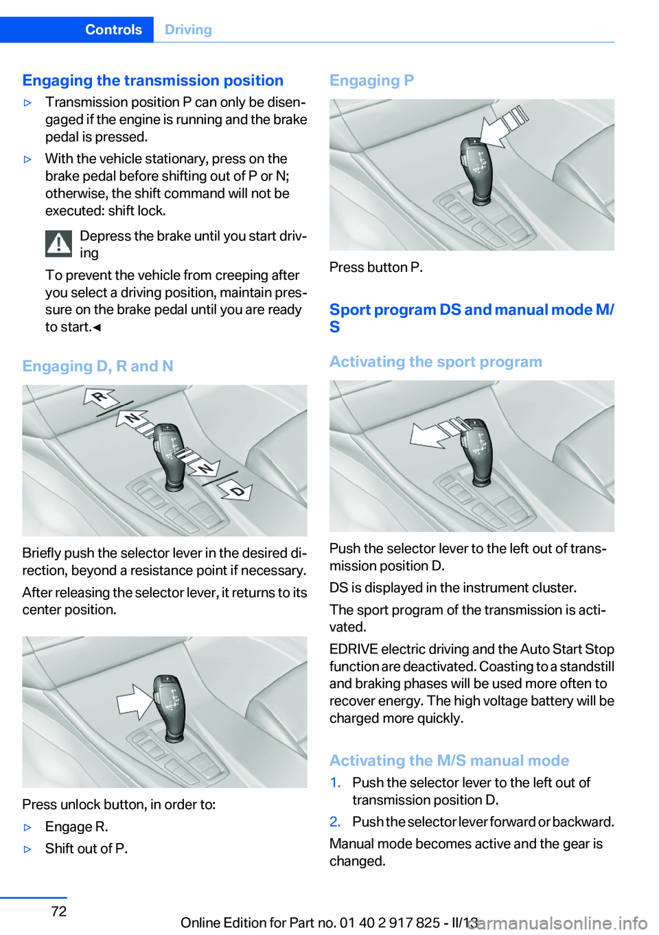
Engaging D, R and N
Briefly push the selector lever in the desired di‐
rection, beyond a resistance point if necessary.
After releasing the selector lever, it returns to its
center position.
Press unlock button, in order to:
▷Engage R.▷Shift out of P.Engaging P
Press button P.
Sport program DS and manual mode M/
S
Activating the sport program
Push the selector lever to the left out of trans‐
mission position D.
DS is displayed in the instrument cluster.
The sport program of the transmission is acti‐
vated.
EDRIVE electric driving and the Auto Start Stop
function are deactivated. Coasting to a standstill
and braking phases will be used more often to
recover energy. The high voltage battery will be
charged more quickly.
Activating the M/S manual mode
1.Push the selector lever to the left out of
transmission position D.2.Push the selector lever forward or backward.
Manual mode becomes active and the gear is
changed.
Seite 72ControlsDriving72
Online Edition for Part no. 01 40 2 917 825 - II/13
Page 73 of 220
The engaged gear is displayed in the instrument
cluster, e.g., M1.
Once maximum engine speed is attained, M/S
manual mode is automatically upshifted as
needed.
Switching to manual mode▷To shift down: press the selector lever for‐
ward.▷To shift up: pull the selector lever rearwards.
Gears will only be shifted at appropriate engine
and road speeds, e.g., downshifting is not pos‐
sible if the engine speed is too high.
The selected gear is briefly displayed in the in‐
strument cluster, followed by the current gear.
Sport automatic transmissions:
prevent automatic upshifting in M/S
manual mode
For vehicles with Sport automatic transmis‐
sions, automatic shift operations are not per‐
formed, at maximum engine speed for example,
if one of the following conditions is met:
▷DSC deactivated.▷TRACTION activated.▷SPORT+ activated.
In addition, the kickdown is deactivated.
Ending the sport program/manual
mode
Push the selector lever to the right.
D is displayed in the instrument cluster.
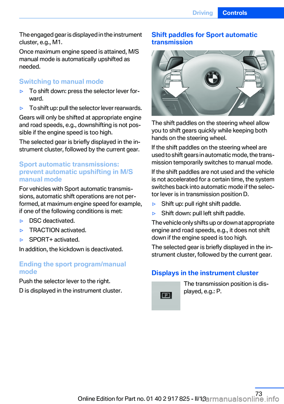
Shift paddles for Sport automatic
transmission
The shift paddles on the steering wheel allow
you to shift gears quickly while keeping both
hands on the steering wheel.
If the shift paddles on the steering wheel are
used to shift gears in automatic mode, the trans‐
mission temporarily switches to manual mode.
If the shift paddles are not used and the vehicle
is not accelerated for a certain time, the system
switches back into automatic mode if the selec‐
tor lever is in transmission position D.
▷Shift up: pull right shift paddle.▷Shift down: pull left shift paddle.
The vehicle only shifts up or down at appropriate
engine and road speeds, e.g., it does not shift
down if the engine speed is too high.
The selected gear is briefly displayed in the in‐
strument cluster, followed by the current gear.
Displays in the instrument cluster The transmission position is dis‐
played, e.g.: P.
Seite 73DrivingControls73
Online Edition for Part no. 01 40 2 917 825 - II/13
Page 81 of 220
the combustion engine upon reaching the des‐
tination zone even before reaching the destina‐
tion. The vehicle is powered only by the electric
motor.
The symbol indicates that the vehicle will
switch off the combustion engine when it enters
the destination zone.
Current fuel consumption
Instrument cluster Displays the current fuel con‐
sumption. You can check
whether you are currently driving
in an efficient and environmen‐
tally-friendly manner.
This display is available in the SPORT driving
mode.
Current consumption can be displayed in the
onboard computer, refer to page 84, in any
driving mode.
Service requirements
The concept
The driving distance or the time to the next
scheduled maintenance is displayed briefly after
the ignition is switched on.
The current service requirements can be read
out from the remote control by the service spe‐
cialist.
Display
Data regarding the service status or legally man‐
dated inspections of the vehicle are automati‐
cally transmitted to your service center before a
service due date.
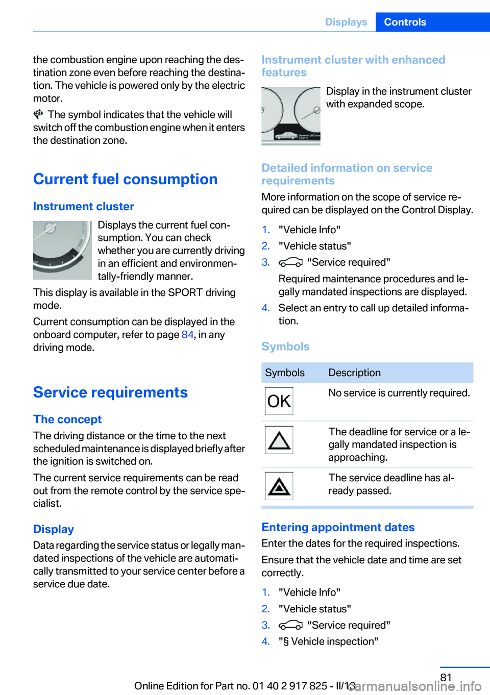
Instrument cluster with enhanced
features
Display in the instrument cluster
with expanded scope.
Detailed information on service
requirements
More information on the scope of service re‐
quired can be displayed on the Control Display.1."Vehicle Info"2."Vehicle status"3. "Service required"
Required maintenance procedures and le‐
gally mandated inspections are displayed.4.Select an entry to call up detailed informa‐
tion.
Symbols
SymbolsDescriptionNo service is currently required.The deadline for service or a le‐
gally mandated inspection is
approaching.The service deadline has al‐
ready passed.
Entering appointment dates
Enter the dates for the required inspections.
Ensure that the vehicle date and time are set
correctly.
1."Vehicle Info"2."Vehicle status"3. "Service required"4."§ Vehicle inspection"Seite 81DisplaysControls81
Online Edition for Part no. 01 40 2 917 825 - II/13
Page 113 of 220
This results in a sporty steering response. In ad‐
dition, it becomes easier to steer during parking
and maneuvering.
Driving Dynamics Control
The concept
The Driving Dynamics Control can be used to
adjust the certain characteristics of the vehicle.
Various programs can be selected for this pur‐
pose. The Driving Dynamics Control and the
DSC OFF buttons can each be used to activate
a program.
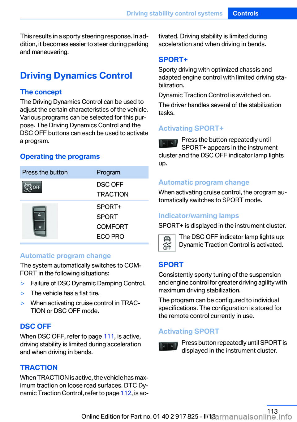
Operating the programsPress the buttonProgramDSC OFF
TRACTIONSPORT+
SPORT
COMFORT
ECO PRO
Automatic program change
The system automatically switches to COM‐
FORT in the following situations:
▷Failure of DSC Dynamic Damping Control.▷The vehicle has a flat tire.▷When activating cruise control in TRAC‐
TION or DSC OFF mode.
DSC OFF
When DSC OFF, refer to page 111, is active,
driving stability is limited during acceleration
and when driving in bends.
TRACTION
When TRACTION is active, the vehicle has max‐
imum traction on loose road surfaces. DTC Dy‐
namic Traction Control, refer to page 112, is ac‐
tivated. Driving stability is limited during
acceleration and when driving in bends.
SPORT+
Sporty driving with optimized chassis and
adapted engine control with limited driving sta‐
bilization.
Dynamic Traction Control is switched on.
The driver handles several of the stabilization
tasks.
Activating SPORT+ Press the button repeatedly until
SPORT+ appears in the instrument
cluster and the DSC OFF indicator lamp lights
up.
Automatic program change
When activating cruise control, the program au‐
tomatically switches to SPORT mode.
Indicator/warning lamps
SPORT+ is displayed in the instrument cluster.
The DSC OFF indicator lamp lights up:
Dynamic Traction Control is activated.
SPORT
Consistently sporty tuning of the suspension
and engine control for greater driving agility with
maximum driving stabilization.
The program can be configured to individual
specifications. The configuration is stored for
the remote control currently in use.
Activating SPORT Press button repeatedly until SPORT is
displayed in the instrument cluster.Seite 113Driving stability control systemsControls113
Online Edition for Part no. 01 40 2 917 825 - II/13
Page 114 of 220
Configuring SPORT
When the display is activated on the Control
Display, refer to page 114, the SPORT driving
mode can be set to individual specifications.▷Activating SPORT.▷"Configure SPORT"▷Configuring the SPORT driving mode.
SPORT can also be configured before it is acti‐
vated:
1."Settings"2."Driving mode"3."Configure SPORT"4.Configure driving mode.
This configuration is retrieved when the SPORT
driving mode is activated.
COMFORT
For a balanced tuning with maximum driving sta‐
bilization.
Activating COMFORT Press button repeatedly until COM‐
FORT is displayed in the instrument
cluster.
In certain situations, the system automatically
changes to the NORMAL program, automatic
program change, refer to page 113.
ECO PRO
ECO PRO, refer to page 160, provides consis‐
tent tuning to minimize fuel consumption for
maximum range with maximum driving stabili‐
zation.
Comfort functions and the engine controller are
adjusted.
The program can be configured to individual
specifications.
Activating ECO PRO
Press button repeatedly until ECO PRO
is displayed in the instrument cluster.
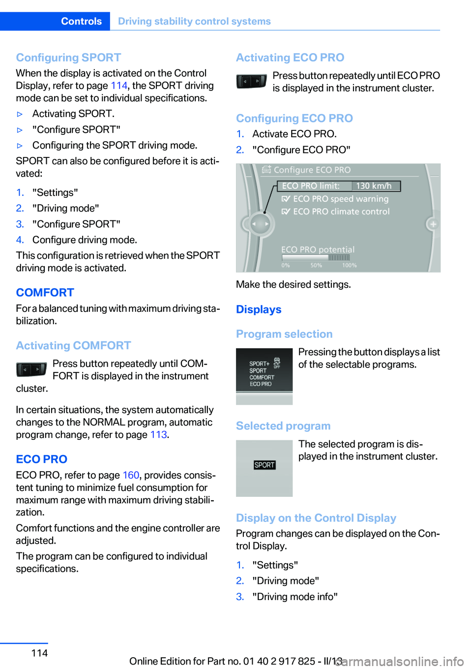
Configuring ECO PRO1.Activate ECO PRO.2."Configure ECO PRO"
Make the desired settings.
Displays
Program selection Pressing the button displays a list
of the selectable programs.
Selected program The selected program is dis‐
played in the instrument cluster.
Display on the Control Display
Program changes can be displayed on the Con‐
trol Display.
1."Settings"2."Driving mode"3."Driving mode info"Seite 114ControlsDriving stability control systems114
Online Edition for Part no. 01 40 2 917 825 - II/13
Page 156 of 220

LoadingVehicle equipment
All standard, country-specific and optional
equipment that is offered in the model series is
described in this chapter. Therefore, equipment
is also described that is not available in a vehicle,
e. g., because of the selected optional equip‐
ment or country variant. This also applies for
safety-related functions and systems.
Hints Overloading the vehicle
To avoid exceeding the approved carrying
capacity of the tires, never overload the vehicle.
Overloading can lead to overheating and in‐
creases the rate at which damage develops in‐
side the tires. This could result in a sudden loss
of tire inflation pressure.◀
No fluids in the trunk
Make sure that fluids do not leak into the
trunk; otherwise, the vehicle may be damaged. ◀
Determining the load limit1.Locate the following statement on your ve‐
hicle’s placard:▷The combined weight of occupants and
cargo should never exceed XXX kg or
YYY lbs. Otherwise, damage to the ve‐hicle and unstable driving situations may
result.2.Determine the combined weight of the
driver and passengers that will be riding in
your vehicle.3.Subtract the combined weight of the driver
and passengers from XXX kilograms or YYY
pounds.4.The resulting figure equals the available
amount of cargo and luggage load capacity.
For example, if the YYY amount equals
1,000 lbs and there will be four 150 lbs pas‐
sengers in your vehicle, the amount of avail‐
able cargo and luggage load capacity is
400 lbs: 1,000 lbs minus 600 lbs = 400 lbs.5.Determine the combined weight of luggage
and cargo being loaded on the vehicle. That
weight may not safely exceed the available
cargo and luggage load capacity calculated
in Step 4.
Load
The maximum load is the sum of the weight of
the occupants and the cargo.
The greater the weight of the occupants, the
less cargo that can be transported.
Seite 156Driving tipsLoading156
Online Edition for Part no. 01 40 2 917 825 - II/13