2013 BMW 128I COUPE indicator
[x] Cancel search: indicatorPage 94 of 284
93
Technology for driving comfort and safety
Controls
System limitations
Sudden serious tire damage caused by
external influences ca
nnot be indicated in
advance.<
The system does not function correctly if it has
not been reset. For example, a flat tire may be
indicated even though the tire inflation pres-
sures are correct.
The system is inactive and cannot indicate a flat
tire:
> When a wheel without TPM electronics is
installed.
> Interference with TPM by other systems or
devices with the same transmission
frequency.
Status display
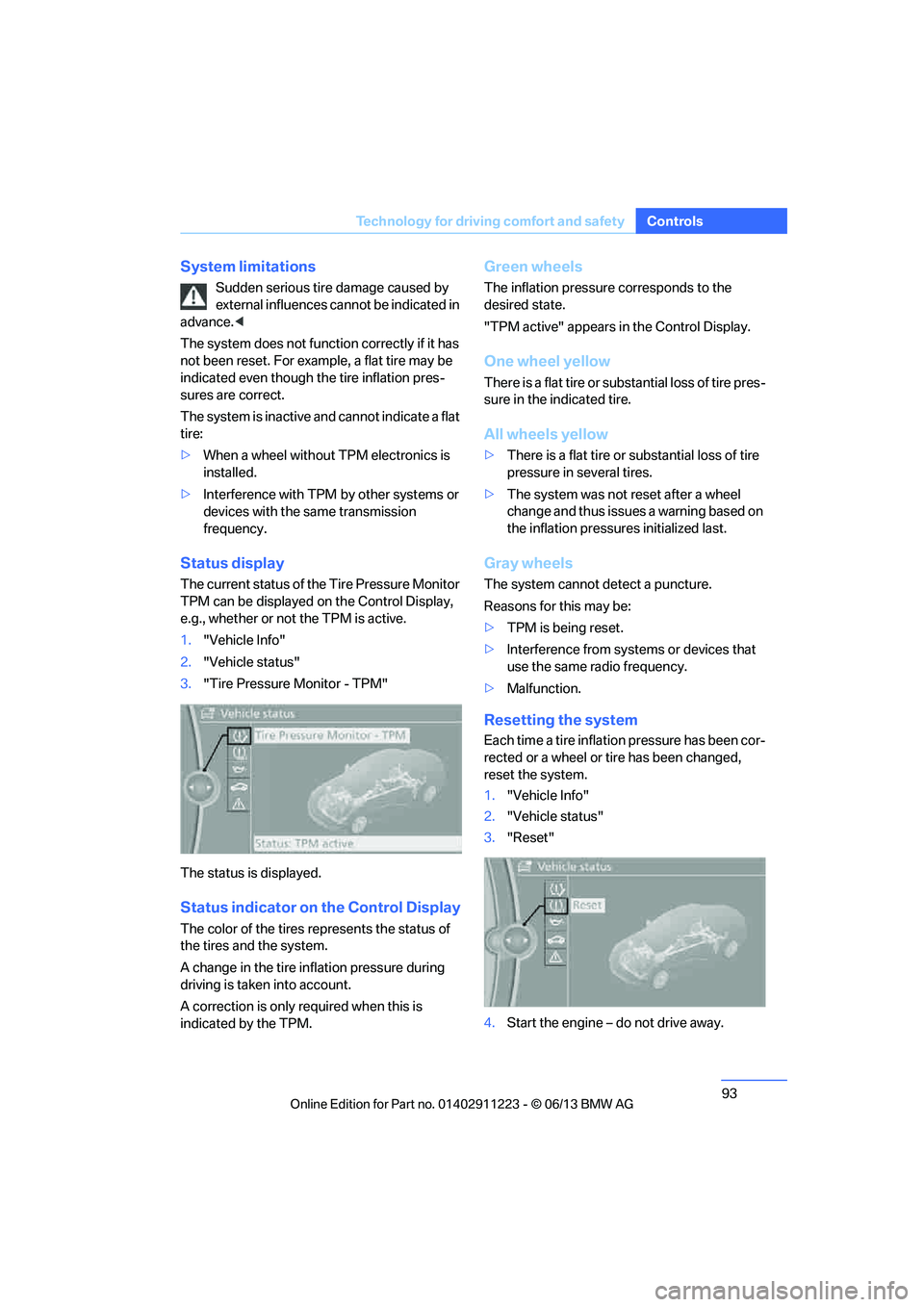
The current status of the Tire Pressure Monitor
TPM can be displayed on the Control Display,
e.g., whether or not the TPM is active.
1. "Vehicle Info"
2. "Vehicle status"
3. "Tire Pressure Monitor - TPM"
The status is displayed.
Status indicator on the Control Display
The color of the tires represents the status of
the tires and the system.
A change in the tire in flation pressure during
driving is taken into account.
A correction is only re quired when this is
indicated by the TPM.
Green wheels
The inflation pressure corresponds to the
desired state.
"TPM active" appears in the Control Display.
One wheel yellow
There is a flat tire or substantial loss of tire pres-
sure in the indicated tire.
All wheels yellow
> There is a flat tire or substantial loss of tire
pressure in several tires.
> The system was not reset after a wheel
change and thus issues a warning based on
the inflation pressure s initialized last.
Gray wheels
The system cannot detect a puncture.
Reasons for this may be:
>TPM is being reset.
> Interference from systems or devices that
use the same radio frequency.
> Malfunction.
Resetting the system
Each time a tire inflation pressure has been cor-
rected or a wheel or tire has been changed,
reset the system.
1."Vehicle Info"
2. "Vehicle status"
3. "Reset"
4. Start the engine – do not drive away.
00320051004F004C00510048000300280047004C0057004C005200510003
Page 96 of 284
95
Technology for driving comfort and safety
Controls
Message for unsuc
cessful system
reset
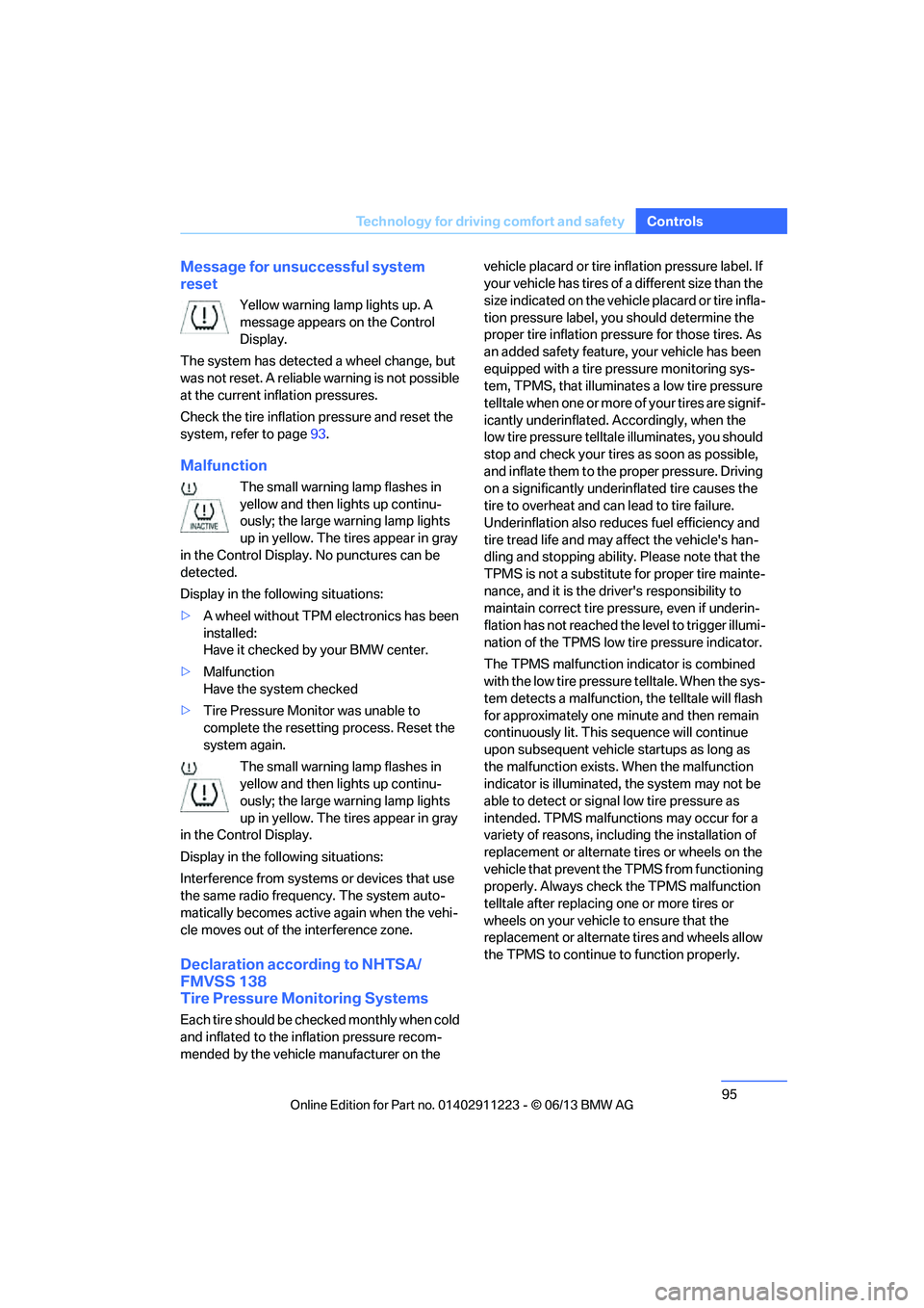
Yellow warning lamp lights up. A
message appears on the Control
Display.
The system has detected a wheel change, but
was not reset. A reliable warning is not possible
at the current inflation pressures.
Check the tire inflation pressure and reset the
system, refer to page 93.
Malfunction
The small warning lamp flashes in
yellow and then lights up continu-
ously; the large warning lamp lights
up in yellow. The tires appear in gray
in the Control Display. No punctures can be
detected.
Display in the following situations:
> A wheel without TPM electronics has been
installed:
Have it checked by your BMW center.
> Malfunction
Have the system checked
> Tire Pressure Monitor was unable to
complete the resetting process. Reset the
system again.
The small warning lamp flashes in
yellow and then lights up continu-
ously; the large warning lamp lights
up in yellow. The tires appear in gray
in the Control Display.
Display in the following situations:
Interference from systems or devices that use
the same radio frequency. The system auto-
matically becomes active again when the vehi-
cle moves out of the interference zone.
Declaration according to NHTSA/
FMVSS 138
Tire Pressure Monitoring Systems
Each tire should be checked monthly when cold
and inflated to the inflation pressure recom-
mended by the vehicle manufacturer on the vehicle placard or tire infl
ation pressure label. If
your vehicle has tires of a different size than the
size indicated on the vehi cle placard or tire infla-
tion pressure label, you should determine the
proper tire inflation pressure for those tires. As
an added safety feature, your vehicle has been
equipped with a tire pr essure monitoring sys-
tem, TPMS, that illuminate s a low tire pressure
t e l l t a l e w h e n o n e o r m o r e o f y o u r t i r e s a r e s i g n i f -
icantly underinflated. Accordingly, when the
low tire pressure telltal e illuminates, you should
stop and check your tires as soon as possible,
and inflate them to the proper pressure. Driving
on a significantly underinflated tire causes the
tire to overheat and ca n lead to tire failure.
Underinflation also reduces fuel efficiency and
tire tread life and may a ffect the vehicle's han-
dling and stopping ability. Please note that the
TPMS is not a substitute for proper tire mainte-
nance, and it is the driver's responsibility to
maintain correct tire pr essure, even if underin-
flation has not reached th e level to trigger illumi-
nation of the TPMS low tire pressure indicator.
The TPMS malfunction indicator is combined
with the low tire pressure telltale. When the sys-
tem detects a malfunction, the telltale will flash
for approximately one minute and then remain
continuously lit. This sequence will continue
upon subsequent vehicle startups as long as
the malfunction exists. When the malfunction
indicator is illuminated, the system may not be
able to detect or signal low tire pressure as
intended. TPMS malfunctions may occur for a
variety of reasons, includ ing the installation of
replacement or alternate tires or wheels on the
vehicle that prevent the TPMS from functioning
properly. Always check the TPMS malfunction
telltale after replacing one or more tires or
wheels on your vehicle to ensure that the
replacement or alternate tires and wheels allow
the TPMS to continue to function properly.
00320051004F004C00510048000300280047004C0057004C005200510003
Page 98 of 284

97
Technology for driving comfort and safety
Controls
Airbags
The following airbags are located under the
marked covers:
1
Front airbags
2 Coupe: head airbags
3 Side airbags in the seat backrests
4 Convertible: knee airbags
Protective action
Observe the adjustment instructions on
page 49 to ensure the best possible
personal protection. <
The front airbags help protect the driver and
front passenger by responding to frontal
impacts in which safety belts alone cannot pro-
vide adequate restrain t. When needed, the
head and side airbags help provide protection in
the event of side impact. The relevant side air-
bag supports the side upper body area. The
head air bag supports the head.
The airbags have been designed to not be trig-
gered in every collision si tuation, e.g. not in
minor accidents or rear-end collisions.
Do not apply adhesive materials to the
cover panels of the airbags, cover them or
modify them in any other way.
Keep the dashboard and window on the front
passenger side clear, i. e., do not cover with
adhesive labels or coveri ngs, and do not attach
holders such as for navigation instruments and
mobile phones.
Do not attach seat cove rs, cushions or other
objects not specifically approved for seats with
integral side airbags to the front seats. Do not
hang items of clothing su ch as coats or jackets over the backrests. Do
not attempt to remove
the airbag retention system from the vehicle. Do
not modify the individu al components of the
system or its wiring in any way. This includes
the upholstered covers on the steering wheel,
instrument panel, seats and roof posts, as well
as the sides of the roof lining. Do not attempt to
remove or dismantle the steering wheel.
Do not touch the individual components imme-
diately after the system has been triggered,
because there is a danger of burns.
In the event of faults, immobilization, or after the
airbag system has been triggered, only have the
testing, repair, or disa ssembly and scrapping of
gas generator performed by your BMW center
or a workshop that has the required explosives
licenses. Unprofessional attempts to work on
the system could lead to failure in an emer-
gency or to undesired ai rbag activation, either
of which could result in personal injury. <
Warning notices and information about the
airbags can also be found on the sun visors.
Automatic deactivation of the front
passenger airbags
An analysis of the impr ession in the front pas-
senger seat cushion determines whether and
how the seat is occupied. The front and side air-
bags for the front passe nger are activated or
deactivated by the system accordingly.
The indicator lamp above the interior
rearview mirror shows the current status
of the front passenger ai rbags, deactivated or
activated, refer to Sta tus of front passenger
airbags below. <
00320051004F004C00510048000300280047004C0057004C005200510003
Page 99 of 284
98
ControlsTechnology for driving comfort and safety
Before transporting a child on the front
passenger seat, read the safety precau-
tions and handling inst ructions under Trans-
porting children safely, refer to page 58.
The front and side airbags can also be deacti-
vated by adolescents and adults sitting in cer-
tain positions; the indi cator lamp for the front
passenger airbags lights up. In such cases, the
passenger should change his or her sitting
position so that the fr ont passenger airbags are
activated and the indicator lamp goes out. If the
desired airbag status cannot be achieved by
changing the sitting position, transport the rele-
vant passenger on a rear seat. Do not attach
seat covers, seat cushion padding, ball mats or
other items to the front passenger seat unless
they are specifically recommended by BMW.
Do not place any items under the seat which
could press against the seat from below. Other-
wise, a correct analysis of the seat cushion is
not ensured. <
Status of front passenger airbags
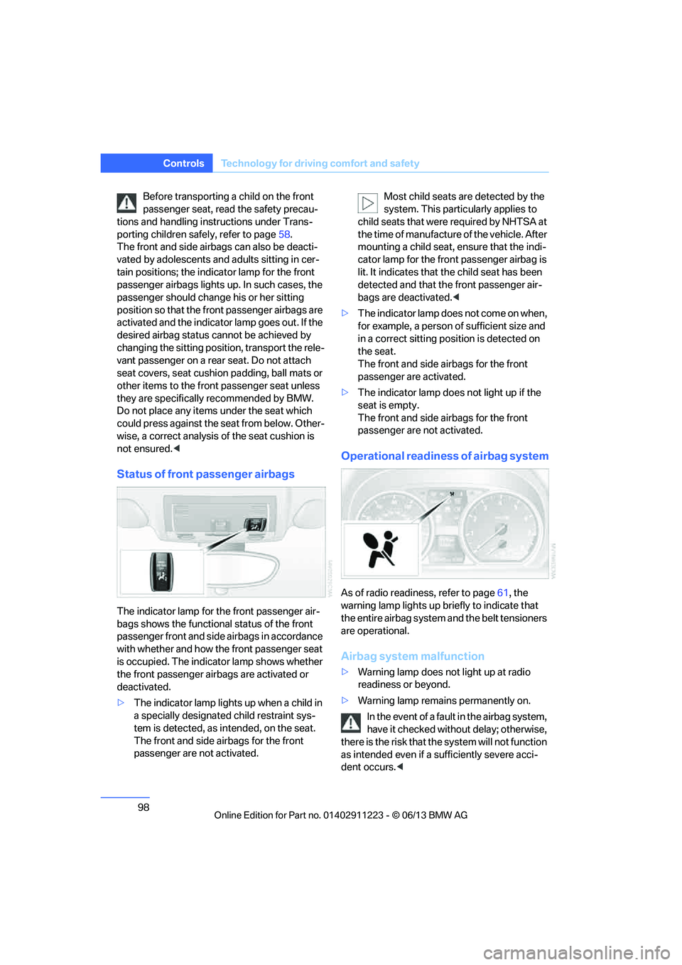
The indicator lamp for the front passenger air-
bags shows the functional status of the front
passenger front and side airbags in accordance
with whether and how the front passenger seat
is occupied. The indicator lamp shows whether
the front passenger airbags are activated or
deactivated.
>The indicator lamp lights up when a child in
a specially designated child restraint sys-
tem is detected, as in tended, on the seat.
The front and side airbags for the front
passenger are not activated. Most child seats are detected by the
system. This partic
ularly applies to
child seats that were required by NHTSA at
the time of manufacture of the vehicle. After
mounting a child seat, ensure that the indi-
cator lamp for the fron t passenger airbag is
lit. It indicates that th e child seat has been
detected and that the front passenger air-
bags are deactivated. <
> The indicator lamp does n o t c o m e o n w h e n ,
for example, a person of sufficient size and
in a correct sitting position is detected on
the seat.
The front and side airbags for the front
passenger are activated.
> The indicator lamp does not light up if the
seat is empty.
The front and side airbags for the front
passenger are not activated.
Operational readine ss of airbag system
As of radio readiness, refer to page 61, the
warning lamp lights up br iefly to indicate that
the entire airbag system and the belt tensioners
are operational.
Airbag system malfunction
> Warning lamp does not light up at radio
readiness or beyond.
> Warning lamp remains permanently on.
In the event of a fault in the airbag system,
have it checked withou t delay; otherwise,
there is the risk that th e system will not function
as intended even if a sufficiently severe acci-
dent occurs. <
00320051004F004C00510048000300280047004C0057004C005200510003
Page 103 of 284

102
ControlsLamps
angle and other parameters, the light from the
headlamp follows the course of the road.
In tight curves such as on switchbacks or when
turning, at speeds up to approx. 40 mph/
70 km/h, an additional, cornering light is
switched on that lights up the area inside the
curve.
Activating Adaptive Light Control
With the ignition switched on, turn the light
switch to position 3, refer to page 100.
The corner-illuminating lamp is switched on
automatically, depending on the steering wheel
angle or turn signal indicator.
Standstill function: to avoid blinding oncoming
traffic, the Adaptive Light Control does not
direct light toward the driver's side when the
vehicle is at a standstill.
When you are reversing, only the corner-illumi-
nating lamps are switched on and active on
both sides.
Malfunction
The warning lamp lights up. A mes-
sage appears on the Control Display.
The Adaptive Light Control is mal-
functioning or failed. Ha ve the system checked
as soon as possible.
High beams/roadside parking
lamps
1 High beams
2 Headlamp flasher
3 Roadside parking lamps
Roadside parking lamps, left or right
There is an additional option of switching on the
lamps on the side of the car facing the road
when parked.
Switching on
After parking the vehicle, press the lever up or
down beyond the pressu re point for approx.
1 second, arrow 3.
The roadside parking lamps drain the bat-
tery. Therefore, do not leave them on for
unduly long periods of time; otherwise, the bat-
tery might not have enou gh power to start the
engine. <
Switching off
Press the lever in the o pposite direction to the
pressure point, arrow 3.
High-beam Assistant
The concept
This system automatically switches the high
beams on and off. The procedure is controlled
by a sensor on the front of the interior rearview
mirror. The assistant ensures that the high
beams are switched on whenever the traffic sit-
uation allows. It handle s this task for you and
gives you the benefit of the best possible view.
You can intervene at any time and switch the
high beams on and off as usual.
Activating the system
1. Turn the light switch to position 3, refer to
page 100.
2. With the low beams switched on, briefly
push the turn signal/high beam lever in the
direction of the high beam.
The indicator lamp in the instrument
cluster lights up when the high beams
are activated. The system automati-
cally switches from hi gh beams to low beams
00320051004F004C00510048000300280047004C0057004C005200510003
Page 105 of 284
104
ControlsLamps
The parking lamps or low beams must
be switched on for the fog lamps to
operate. The green indicator lamp in
the instrument cluster lights up whenever the
fog lamps are on.
The fog lamps are switched off while you acti-
vate the headlamp flasher or switch on the high
beams.
If the automatic headla mp control is acti-
vated, the low beams will come on auto-
matically when you swit ch on the fog lamps.<
Instrument lighting
You can adjust the brightness of the instrument
lighting only when the parking lamps or the low
beams are switched on.
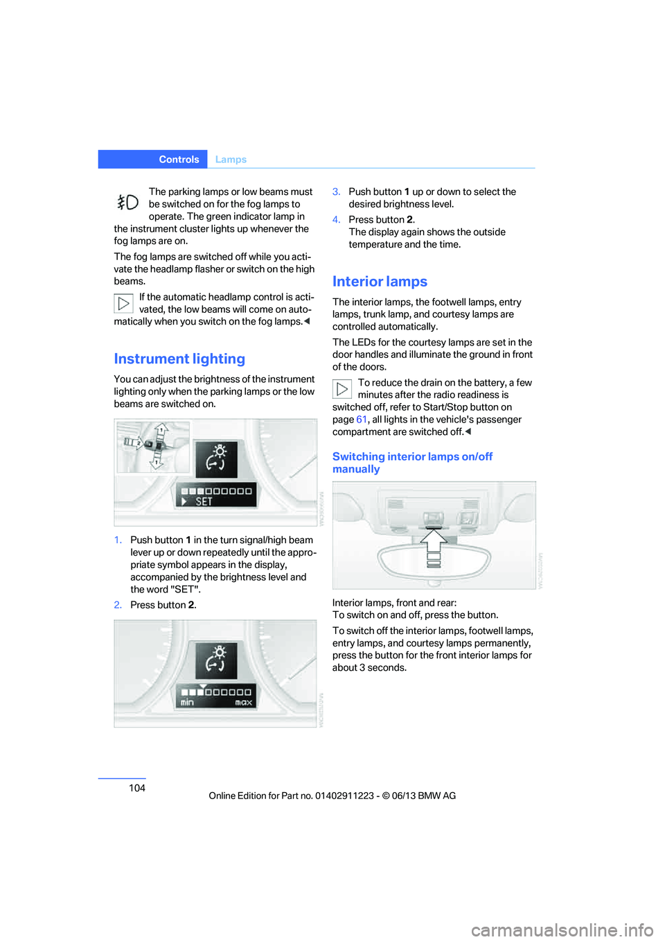
1.Push button 1 in the turn signal/high beam
lever up or down repe atedly until the appro-
priate symbol appear s in the display,
accompanied by the brightness level and
the word "SET".
2. Press button 2. 3.
Push button 1 up or down to select the
desired brightness level.
4. Press button 2.
The display again shows the outside
temperature and the time.
Interior lamps
The interior lamps, the footwell lamps, entry
lamps, trunk lamp, and courtesy lamps are
controlled automatically.
The LEDs for the courtesy lamps are set in the
door handles and illuminate the ground in front
of the doors.
To reduce the drain on the battery, a few
minutes after the radio readiness is
switched off, refer to Start/Stop button on
page 61, all lights in the vehicle's passenger
compartment are switched off. <
Switching interior lamps on/off
manually
Interior lamps, front and rear:
To switch on and off, press the button.
To switch off the interior lamps, footwell lamps,
entry lamps, and courtesy lamps permanently,
press the button for the front interior lamps for
about 3 seconds.
00320051004F004C00510048000300280047004C0057004C005200510003
Page 230 of 284
229
Wheels and tires
Mobility
The traction grade assigned to this tire is
based on straight-ahe
ad braking traction
tests, and does not include acceleration,
cornering, hydroplaning, or peak traction
characteristics. <
Temperature
The temperature grades are A, the highest, B,
and C, representing the ti re's resistance to the
generation of heat and its ability to dissipate
heat when tested under controlled conditions
on a specified indoor laboratory test wheel.
Sustained high temperature can cause the
material of the tire to degenerate and reduce
tire life, and excessive temperature can lead to
sudden tire failure. The grade C corresponds to
a level of performance which all passenger car
tires must meet under the Federal Motor Vehi-
cle Safety Standard No. 109. Grades B and A
represent higher levels of performance on the
laboratory test whee l than the minimum
required by law.
The temperature grade for this tire is
established for a tire that is properly
inflated and not overloaded. Excessive speed,
underinflation, or exce ssive loading, either
separately or in combin ation, can cause heat
buildup and possible tire failure. <
RSC – run-flat tires
You will recognize run-flat tires by a circular
symbol containing the letters RSC on the side
of the tire, refer to page230.
M+S
Winter and all-season tires.
These have better wint er properties than
summer tires.
XL
Designation for specia lly reinforced tires.
Tire condition
Inspect your tires frequently for tread wear,
signs of damage and for foreign objects lodged
in the tread. Check the tread depth.
Minimum tread depth
The tread depth should not drop below 0.12 in/
3 mm, although, for example, European legisla-
tion only specifies a minimum tread depth of
0.063 in/1.6 mm. At tread depths below 0.12 in/
3 mm there is an increased risk of high-speed
hydroplaning, even when only small amounts of
water are present on the road surface.
When winter tires wear down past a tread depth
of 0.16 in/4 mm, they be come perceptibly less
suitable for winter condit ions. In the interest of
safety, new tires sh ould be installed.
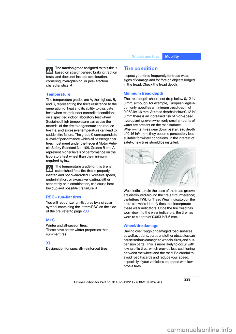
Wear indicators in the base of the tread groove
are distributed around th e tire's circumference;
the letters TWI, for Tread Wear Indicator, on the
tire's sidewalls identify tires that incorporate
these wear indicators. On ce the tire tread has
worn down to the wear indicators, the tire has
worn to a depth of 0.063 in/1.6 mm.
Wheel/tire damage
Driving over rough or damaged road surfaces,
as well as debris, curbs and other obstacles can
cause serious damage to wheels, tires, and sus-
pension parts. This is more likely to occur with
low-profile tires, which provide less cushioning
between the wheel and th e road. Be careful to
avoid road hazards and reduce your speed,
especially if your vehi cle is equipped with low-
profile tires.
00320051004F004C00510048000300280047004C0057004C005200510003
Page 237 of 284
236
MobilityEngine compartment
Coolant temperature
If the coolant and therefore the engine over-
heats, a warning lamp lights up. A message
appears on the Control Display.
Checking coolant level
Do not add coolant to the cooling system
when the engine is ho t. Escaping coolant
can cause burns. <
1. Do not open the engine hood before the
engine has cooled down.
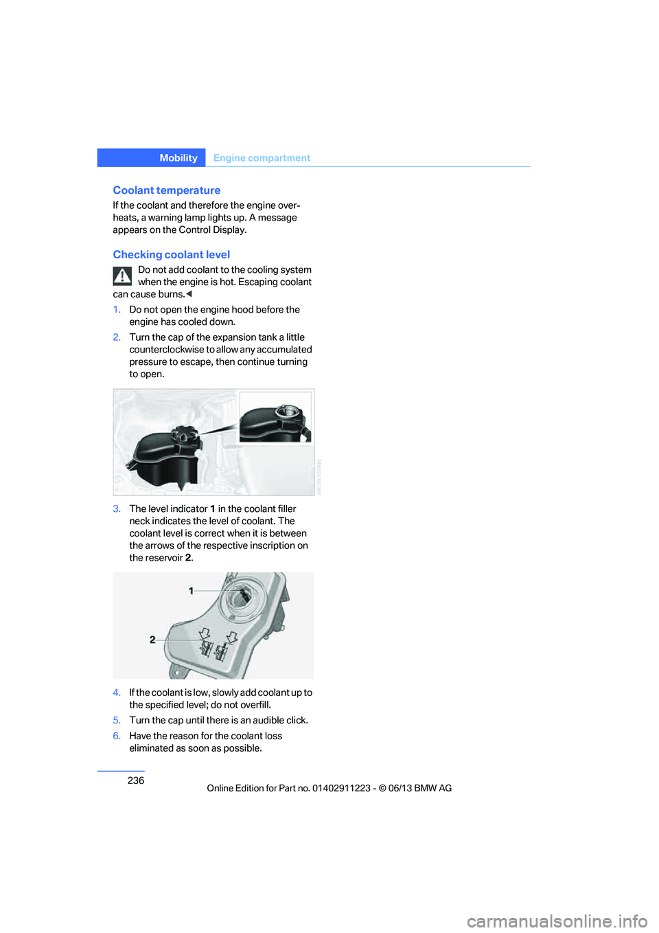
2. Turn the cap of the expansion tank a little
counterclockwise to allow any accumulated
pressure to escape, th en continue turning
to open.
3. The level indicator 1 in the coolant filler
neck indicates the level of coolant. The
coolant level is correct when it is between
the arrows of the respective inscription on
the reservoir 2.
4. If the coolant is low, sl owly add coolant up to
the specified level; do not overfill.
5. Turn the cap until there is an audible click.
6. Have the reason for the coolant loss
eliminated as so on as possible.
00320051004F004C00510048000300280047004C0057004C005200510003