Page 33 of 112
INSTRUMENT AND CONTROL FUNCTIONS
3-18
3
To adjust the shift timing indicator light
brightness1. Push the “RESET” button to select
the desired indicator light bright-
ness level.
2. Push the “SELECT” button to con- firm the selected indicator light
brightness level. The display re-
turns to the odometer or tripmeter
mode.
EAU12331
Anti-theft alarm (optional) This model can be equipped with an
optional anti-theft alarm by a Yamaha
dealer. Contact a Yamaha dealer for
more information.
EAU12349
Handlebar switches Left1. Pass switch “ ”
2. Dimmer switch “ / ”
3. Turn signal switch “ / ”
4. Horn switch “ ”
5. Traction control system switch “TCS”
53421
U1KBE0E0.book Page 18 Monday, July 25, 2011 5:03 PM
Page 34 of 112

INSTRUMENT AND CONTROL FUNCTIONS
3-19
3Right
Hazard switch
EAU12380
Pass switch “ ”
Press this switch to flash the head-
lights.
EAU12400
Dimmer switch “ / ”
Set this switch to “ ” for the high
beam and to “ ” for the low beam.
EAU12460
Turn signal switch “ / ”
To signal a right-hand turn, push this
switch to “ ”. To signal a left-hand
turn, push this switch to “ ”. When re-
leased, the switch returns to the center
position. To cancel the turn signal
lights, push the switch in after it has re-
turned to the center position.
EAU12500
Horn switch “ ”
Press this switch to sound the horn.
EAU51841
Traction control system switch
“TCS”
This switch is used to select the traction
control system modes.
See “Traction control system” on page
3-22 for detailed information.
EAU12660
Engine stop switch “ / ”
Set this switch to “ ” before starting
the engine. Set this switch to “ ” to
stop the engine in case of an emergen-
cy, such as when the vehicle overturns
or when the throttle cable is stuck.
EAU12711
Start switch “ ”
Push this switch to crank the engine
with the starter. See page 5-1 for start-
ing instructions prior to starting the en-
gine.
EAU41700
The engine trouble warning light will
come on when the key is turned to “ON”
and the start switch is pushed, but this
does not indicate a malfunction.
EAU12733
Hazard switch “ ”
With the key in the “ON” or “ ” posi-
tion, use this switch to turn on the haz-
ard lights (simultaneous flashing of all
turn signal lights).
The hazard lights are used in case of
an emergency or to warn other drivers
when your vehicle is stopped where it
might be a traffic hazard.
1. Engine stop switch “ / ”
2. Drive mode switch “MODE”
3. Start switch “ ”
1. Hazard switch “ ”
213
1
U1KBE0E0.book Page 19 Monday, July 25, 2011 5:03 PM
Page 35 of 112

INSTRUMENT AND CONTROL FUNCTIONS
3-20
3
NOTICE
ECA10061
Do not use the hazard lights for an
extended length of time with the en-
gine not running, otherwise the bat-
tery may discharge.
EAU47494
Drive mode switch “MODE”
WARNING
EWA15340
Do not change the D-mode while the
vehicle is moving.Using this switch changes the drive
mode to “STD”, “A”, or “B” in the follow-
ing order:
STD → A → B → STD
The throttle grip must be completely
closed in order to change the drive
mode. (See page 3-1 for an explana-
tion of each drive mode.)TIP●
The mode is set to “STD” by de-
fault. The “STD” mode resets
when the key is turned to “OFF”.
●
The selected mode is shown on
the drive mode display. (See page
3-14.)
EAU12820
Clutch lever The clutch lever is located at the left
handlebar grip. To disengage the
clutch, pull the lever toward the handle-
bar grip. To engage the clutch, release
the lever. The lever should be pulled
rapidly and released slowly for smooth
clutch operation.
The clutch lever is equipped with a
clutch switch, which is part of the igni-
tion circuit cut-off system. (See page
3-36.)
EAU12871
Shift pedal The shift pedal is located on the left
side of the motorcycle and is used in
combination with the clutch lever when
shifting the gears of the 6-speed con-
stant-mesh transmission equipped on
this motorcycle.
1. Clutch lever
1. Shift pedal
1
U1KBE0E0.book Page 20 Monday, July 25, 2011 5:03 PM
Page 36 of 112
INSTRUMENT AND CONTROL FUNCTIONS
3-21
3
EAU33851
Brake lever The brake lever is located at the right
handlebar grip. To apply the front
brake, pull the lever toward the handle-
bar grip.
The brake lever is equipped with a
brake lever position adjusting knob. To
adjust the distance between the brake
lever and the handlebar grip, turn the
adjusting knob while holding the lever
pushed away from the handlebar grip.
When the desired position is obtained,be sure to set it by aligning a groove on
the adjusting knob with the “ ” mark
on the brake lever.
EAU12941
Brake pedal The brake pedal is on the right side of
the motorcycle. To apply the rear
brake, press down on the brake pedal.
1. Brake lever
2. Brake lever position adjusting knob
3. Distance between brake lever and handlebar
grip
4. “ ” mark
4 2
1
3
1. Brake pedal
1
U1KBE0E0.book Page 21 Monday, July 25, 2011 5:03 PM
Page 37 of 112

INSTRUMENT AND CONTROL FUNCTIONS
3-22
3
EAU51861
Traction control system The traction control system helps main-
tain traction when accelerating. If sen-
sors detect that the rear wheel is
starting to slip (uncontrolled spinning),
the traction control system assists by
regulating engine power as needed un-
til traction is restored. The traction con-
trol system indicator/warning light
flashes to let the rider know that traction
control has engaged.
WARNING
EWA15431
The traction control system is not a
substitute for riding appropriately
for the conditions. Traction control
cannot prevent loss of traction due
to excessive speed when entering
turns, when accelerating hard at a
sharp lean angle, or while braking,
and cannot prevent front wheel slip-
ping. As with any motorcycle, ap-
proach surfaces that may be
slippery with caution and avoid es-
pecially slippery surfaces.
TIP●
The traction control may engage
when the vehicle travels over a
bump.
●
The rider may notice slight chang-
es in engine and exhaust sounds
when the traction control system is
engaged.
There are six traction control system
modes and an off mode.●
“TCS” mode 1 provides for the
least traction control system as-
sist.
●
“TCS” modes 2 through 6 provide
for more traction control system
assist. Mode 6 provides the most
traction control system assist.
●
“TCS OFF” mode turns the traction
control system off. The system
may also be automatically dis-
abled in some riding conditions
(see “Resetting” on page 3-23).
When the key is turned to “ON”, the
traction control system is enabled and
the last mode selected displays in the
multi-function meter.
All traction control system modes can
be selected when the key is in the “ON”
position. Modes 1 through 6 can also
be selected when the vehicle is moving,
however the throttle grip must be com-
pletely closed. The traction control sys-
tem cannot be turned on or off while the
vehicle is moving.
NOTICE
ECA16800
Use only the specified tires. (See
page 6-18.) Using different sized
tires will prevent the traction control
system from controlling tire rotation
accurately.
OFF Display
Mode 1
Mode 2
Mode 3
Mode 4
Mode 5
Mode 6
TCS
OFF
TCSTCSTCSTCSTCSTCS
U1KBE0E0.book Page 22 Monday, July 25, 2011 5:03 PM
Page 38 of 112

INSTRUMENT AND CONTROL FUNCTIONS
3-23
3Setting the traction control system
WARNING
EWA16070
Changing settings while riding can
distract the operator. Therefore, take
extra precaution when changing
modes while riding.When the vehicle is stopped, push the
upper side of the traction control sys-
tem switch for at least two seconds to
turn the traction control system off.
Push the lower side of the switch to turn
the traction control system on.
When the vehicle is stopped or while
riding, close the throttle and push the
lower side of the switch to change from
modes 1 to 6. Close the throttle and
push the upper side of the switch to
change from modes 6 to 1.TIPThe vehicle was set to “TCS” mode 6 at
the time of manufacture.
Resetting
The traction control system may be dis-
abled in the following conditions:●
Either the front wheel or rear wheel
comes off the ground while riding
●
Excessive rear wheel spinning If the traction control system has been
disabled, both the traction control sys-
tem indicator/warning light and the en-
gine trouble warning light come on.
To reset the traction control system:
Turn the key to “OFF”. Wait at least one
second, then turn the key back to “ON”.
The traction control system indica-
tor/warning light should go off and the
system will be enabled. The engine
trouble warning light should go off after
the motorcycle reaches at least 20
km/h (12 mi/h). If the traction control
system indicator/warning light and/or
engine trouble warning light still remain
on after resetting, the motorcycle may
still be ridden; however, have a
Yamaha dealer check the motorcycle as soon as possible.NOTICE
ECA17731
●
Keep any type of magnets (in-
cluding magnetic pick-up tools,
magnetic screwdrivers, etc.)
away from the front wheel sen-
sor or rotor; otherwise, the sen-
sor or rotor may be damaged,
1. Traction control system mode display
1. Traction control system switch “TCS”
1
1
U1KBE0E0.book Page 23 Monday, July 25, 2011 5:03 PM
Page 39 of 112

INSTRUMENT AND CONTROL FUNCTIONS
3-24
3
resulting in improper perfor-
mance of the traction control
system.
●
Be careful not to damage the
sensor or rotor.
EAU13074
Fuel tank cap To open the fuel tank cap
Open the fuel tank cap lock cover, in-
sert the key into the lock, and then turn
it 1/4 turn clockwise. The lock will be re-
leased and the fuel tank cap can be
opened.
To close the fuel tank cap
1. Push the fuel tank cap into position with the key inserted in the lock.
2. Turn the key counterclockwise to the original position, remove it, and
then close the lock cover.
TIPThe fuel tank cap cannot be closed un-
less the key is in the lock. In addition,
the key cannot be removed if the cap is
not properly closed and locked.
WARNING
EWA11091
Make sure that the fuel tank cap is
properly closed after filling fuel.
Leaking fuel is a fire hazard.
1. Front wheel sensor rotor
2. Front wheel sensor
2
1
1. Fuel tank cap lock cover
2. Unlock.
U1KBE0E0.book Page 24 Monday, July 25, 2011 5:03 PM
Page 40 of 112

INSTRUMENT AND CONTROL FUNCTIONS
3-25
3
EAU13221
Fuel Make sure there is sufficient gasoline in
the tank.
WARNING
EWA10881
Gasoline and gasoline vapors are
extremely flammable. To avoid fires
and explosions and to reduce the
risk of injury when refueling, follow
these instructions.1. Before refueling, turn off the en-gine and be sure that no one is sit-
ting on the vehicle. Never refuel
while smoking, or while in the vi-
cinity of sparks, open flames, or
other sources of ignition such as
the pilot lights of water heaters and
clothes dryers.
2. Do not overfill the fuel tank. When refueling, be sure to insert the
pump nozzle into the fuel tank filler
hole. Stop filling when the fuel
reaches the bottom of the filler
tube. Because fuel expands when
it heats up, heat from the engine or
the sun can cause fuel to spill out
of the fuel tank. 3. Wipe up any spilled fuel immedi-
ately. NOTICE: Immediately wipe
off spilled fuel with a clean, dry,
soft cloth, since fuel may deteri-
orate painted surfaces or plastic
parts.
[ECA10071]
4. Be sure to securely close the fuel tank cap.
WARNING
EWA15151
Gasoline is poisonous and can
cause injury or death. Handle gaso-
line with care. Never siphon gaso-
line by mouth. If you should swallow
some gasoline or inhale a lot of gas-
oline vapor, or get some gasoline in
your eyes, see your doctor immedi- ately. If gasoline spills on your skin,
wash with soap and water. If gaso-
line spills on your clothing, change
your clothes.
EAU13391
NOTICE
ECA11400
Use only unleaded gasoline. The use
of leaded gasoline will cause severe
damage to internal engine parts,
such as the valves and piston rings,
as well as to the exhaust system.Your Yamaha engine has been de-
signed to use premium unleaded gaso-
line with a research octane number of
95 or higher. If knocking (or pinging) oc-
curs, use a gasoline of a different
1. Fuel tank filler tube
2. Maximum fuel level
2
1
Recommended fuel:
Premium unleaded gasoline only
Fuel tank capacity: 18.0 L (4.76 US gal, 3.96 Imp.gal)
Fuel reserve amount (when the fuel
level warning light comes on): 3.1 L (0.82 US gal, 0.68 Imp.gal)
U1KBE0E0.book Page 25 Monday, July 25, 2011 5:03 PM
 1
1 2
2 3
3 4
4 5
5 6
6 7
7 8
8 9
9 10
10 11
11 12
12 13
13 14
14 15
15 16
16 17
17 18
18 19
19 20
20 21
21 22
22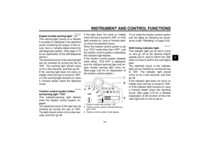 23
23 24
24 25
25 26
26 27
27 28
28 29
29 30
30 31
31 32
32 33
33 34
34 35
35 36
36 37
37 38
38 39
39 40
40 41
41 42
42 43
43 44
44 45
45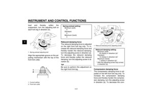 46
46 47
47 48
48 49
49 50
50 51
51 52
52 53
53 54
54 55
55 56
56 57
57 58
58 59
59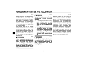 60
60 61
61 62
62 63
63 64
64 65
65 66
66 67
67 68
68 69
69 70
70 71
71 72
72 73
73 74
74 75
75 76
76 77
77 78
78 79
79 80
80 81
81 82
82 83
83 84
84 85
85 86
86 87
87 88
88 89
89 90
90 91
91 92
92 93
93 94
94 95
95 96
96 97
97 98
98 99
99 100
100 101
101 102
102 103
103 104
104 105
105 106
106 107
107 108
108 109
109 110
110 111
111
