Page 73 of 112

PERIODIC MAINTENANCE AND ADJUSTMENT
6-14
6
10. Start the engine, and then let it idle
for several minutes while checking
it for oil leakage. If oil is leaking, im-
mediately turn the engine off and
check for the cause.
TIPAfter the engine is started, the engine
oil level warning light should go off if the
oil level is sufficient.NOTICE
ECA10401
If the oil level warning light flickers
or remains on even if the oil level is
correct, immediately turn the engine
off and have a Yamaha dealer check
the vehicle.11. Turn the engine off, wait a few min-utes until the oil settles, and then
check the oil level and correct it if
necessary.
12. Install the cowlings.
EAU20070
Coolant The coolant level should be checked
before each ride. In addition, the cool-
ant must be changed at the intervals
specified in the periodic maintenance
and lubrication chart.
EAU38173
To check the coolant level 1. Place the vehicle on a level sur- face and hold it in an upright posi-
tion.TIP●
The coolant level must be checked
on a cold engine since the level
varies with engine temperature.
●
Make sure that the vehicle is posi-
tioned straight up when checking
the coolant level. A slight tilt to the
side can result in a false reading.
2. Check the coolant level in the cool-ant reservoir.TIPThe coolant should be between the
minimum and maximum level marks.
3. If the coolant is at or below theminimum level mark, remove the
coolant reservoir cover by remov-
ing the bolts, remove the coolant
reservoir cap, and then add cool-
ant to the maximum level mark.
WARNING! Remove only the coolant reservoir cap. Never at-
tempt to remove the radiator
cap when the engine is hot.
[EWA15161]
NOTICE: If coolant is not
available, use distilled water or
soft tap water instead. Do not
use hard water or salt water
since it is harmful to the engine.
If water has been used instead
1. Coolant reservoir
2. Maximum level mark
3. Minimum level mark
1
3 2
U1KBE0E0.book Page 14 Monday, July 25, 2011 5:03 PM
Page 74 of 112

PERIODIC MAINTENANCE AND ADJUSTMENT
6-15
6of coolant, replace it with cool-
ant as soon as possible, other-
wise the cooling system will not
be protected against frost and
corrosion. If water has been
added to the coolant, have a
Yamaha dealer check the anti-
freeze content of the coolant as
soon as possible, otherwise the
effectiveness of the coolant will
be reduced.
[ECA10472]
4. Install the reservoir cap, and then
install the coolant reservoir cover
by installing the bolts.
EAU47303
To change the coolant1. Place the vehicle on a level sur- face and let the engine cool if nec-
essary.
2. Remove cowlings B and C. (See page 6-8.)
3. Place a container under the engine to collect the used coolant. 4. Remove the radiator cap.
WARNING! Never attempt to re-
move the radiator cap when the
engine is hot.
[EWA10381]
5. Remove the coolant drain bolt andits gasket to drain the cooling sys-
tem.
1. Coolant reservoir cover
2. Bolt
1
2
1. Coolant reservoir capCoolant reservoir capacity (up to
the maximum level mark): 0.25 L (0.26 US qt, 0.22 Imp.qt)
1
1. Radiator cap
1. Coolant drain bolt
2. Gasket
1
12
U1KBE0E0.book Page 15 Monday, July 25, 2011 5:03 PM
Page 75 of 112

PERIODIC MAINTENANCE AND ADJUSTMENT
6-16
6
6. Remove the coolant reservoir cov-
er by removing the bolts, and then
remove the coolant reservoir cap. 7. Remove the coolant reservoir by
removing the bolts, and then turn
the reservoir upside down to emp-
ty it.
8. After the coolant is completely drained, thoroughly flush the cool-
ing system with clean tap water.
9. Install the coolant reservoir by in- stalling the bolts.
10. Install the coolant drain bolt and its new gasket, and then tighten the
bolt to the specified torque. 11. Pour the recommended coolant
into the reservoir to the maximum
level mark, and then install the
coolant reservoir cap.
12. Pour the recommended coolant into the radiator until it is full.
13. Install the radiator cap, start the engine, let it idle for several min-
utes, and then turn it off.
14. Remove the radiator cap to check the coolant level in the radiator. If
necessary, add sufficient coolant
until it reaches the top of the radia-
tor, and then install the radiator
cap.
1. Coolant reservoir cover
2. Bolt
1. Coolant reservoir cap
1
2
1
1. Coolant reservoir
2. Bolt
Tightening torque:Coolant drain bolt:7 Nm (0.7 m·kgf, 5.1 ft·lbf)
1
2
Antifreeze/water mixture ratio:1:1
Recommended antifreeze: High-quality ethylene glycol anti-
freeze containing corrosion inhibi-
tors for aluminum engines
Coolant quantity:
Radiator capacity (including all
routes): 2.73 L (2.89 US qt, 2.40 Imp.qt)
Coolant reservoir capacity (up to the
maximum level mark): 0.25 L (0.26 US qt, 0.22 Imp.qt)
U1KBE0E0.book Page 16 Monday, July 25, 2011 5:03 PM
Page 76 of 112
PERIODIC MAINTENANCE AND ADJUSTMENT
6-17
615. Start the engine, and then check
the vehicle for coolant leakage. If
coolant is leaking, have a Yamaha
dealer check the cooling system.
16. Install the coolant reservoir cover by installing the bolts.
17. Install the cowlings.
EAU36764
Air filter element The air filter element must be replaced
at the intervals specified in the periodic
maintenance and lubrication chart.
Have a Yamaha dealer replace the air
filter element.
EAU44734
Checking the engine idling
speed Check the engine idling speed and, if
necessary, have it corrected by a
Yamaha dealer.Engine idling speed: 1150–1250 r/min
U1KBE0E0.book Page 17 Monday, July 25, 2011 5:03 PM
Page 77 of 112
 at the
inner edge of the throttle g")
PERIODIC MAINTENANCE AND ADJUSTMENT
6-18
6
EAU21384
Checking the throttle grip free
play The throttle grip free play should mea-
sure 3.0–5.0 mm (0.12–0.20 in) at the
inner edge of the throttle grip. Periodi-
cally check the throttle grip free play
and, if necessary, have a Yamaha deal-
er adjust it.
EAU21401
Valve clearance The valve clearance changes with use,
resulting in improper air-fuel mixture
and/or engine noise. To prevent this
from occurring, the valve clearance
must be adjusted by a Yamaha dealer
at the intervals specified in the periodic
maintenance and lubrication chart.
EAU21775
Tires To maximize the performance, durabil-
ity, and safe operation of your motorcy-
cle, note the following points regarding
the specified tires.
Tire air pressure
The tire air pressure should be checked
and, if necessary, adjusted before each
ride.
WARNING
EWA10503
Operation of this vehicle with im-
proper tire pressure may cause se-
vere injury or death from loss of
control.●
The tire air pressure must be
checked and adjusted on cold
tires (i.e., when the temperature
of the tires equals the ambient
temperature).
●
The tire air pressure must be ad-
justed in accordance with the
riding speed and with the total
weight of rider, passenger, car-
go, and accessories approved
for this model.
1. Throttle grip free play
1
U1KBE0E0.book Page 18 Monday, July 25, 2011 5:03 PM
Page 78 of 112

PERIODIC MAINTENANCE AND ADJUSTMENT
6-19
6
WARNING
EWA10511
Never overload your vehicle. Opera-
tion of an overloaded vehicle could
cause an accident.
Tire inspection
The tires must be checked before each
ride. If the center tread depth reaches
the specified limit, if the tire has a nail or
glass fragments in it, or if the sidewall is
cracked, have a Yamaha dealer re-
place the tire immediately.TIPThe tire tread depth limits may differ
from country to country. Always comply
with the local regulations.
WARNING
EWA10471
●
Have a Yamaha dealer replace
excessively worn tires. Besides
being illegal, operating the vehi-
cle with excessively worn tires
decreases riding stability and
can lead to loss of control.
●
The replacement of all wheel
and brake-related parts, includ-
ing the tires, should be left to a
Yamaha dealer, who has the
necessary professional knowl-
edge and experience to do so.
●
Ride at moderate speeds after
changing a tire since the tire
surface must first be “broken
in” for it to develop its optimal
characteristics.
Tire air pressure (measured on cold
tires):0–90 kg (0–198 lb):Front:
250 kPa (2.50 kgf/cm², 36 psi)
Rear: 290 kPa (2.90 kgf/cm², 42 psi)
90–189 kg (198–417 lb): Front:250 kPa (2.50 kgf/cm², 36 psi)
Rear: 290 kPa (2.90 kgf/cm², 42 psi)
High-speed riding:
Front:250 kPa (2.50 kgf/cm², 36 psi)
Rear:
290 kPa (2.90 kgf/cm², 42 psi)
Maximum load*: 189 kg (417 lb)
* Total weight of rider, passenger, car- go and accessories
1. Tire sidewall
2. Tire tread depthMinimum tire tread depth (front and
rear): 1.6 mm (0.06 in)
U1KBE0E0.book Page 19 Monday, July 25, 2011 5:03 PM
Page 79 of 112

PERIODIC MAINTENANCE AND ADJUSTMENT
6-20
6
Tire information
This motorcycle is equipped with tube-
less tires, tire air valves and cast
wheels.
WARNING
EWA10481
●
The front and rear tires should
be of the same make and de-
sign, otherwise the handling
characteristics of the motorcy-
cle may be different, which
could lead to an accident.
●
Always make sure that the valve
caps are securely installed to
prevent air pressure leakage.
●
Use only the tire valves and
valve cores listed below to
avoid tire deflation during a
high-speed ride.
After extensive tests, only the tires list-
ed below have been approved for this
model by Yamaha Motor Co., Ltd.
WARNING
EWA10600
This motorcycle is fitted with super-
high-speed tires. Note the following
points in order to make the most ef-
ficient use of these tires.●
Use only the specified replace-
ment tires. Other tires may run
the danger of bursting at super
high speeds.
●
Brand-new tires can have a rela-
tively poor grip on certain road
surfaces until they have been
“broken in”. Therefore, it is ad-
visable before doing any high-
speed riding to ride conserva-
tively for approximately 100 km
(60 mi) after installing a new tire.
●
The tires must be warmed up
before a high-speed run.
●
Always adjust the tire air pres-
sure according to the operating
conditions.
1. Tire air valve
2. Tire air valve core
3. Tire air valve cap with seal
Front tire:
Size:120/70 ZR17M/C (58W)
Manufacturer/model: MICHELIN/POWER PURE A
DUNLOP/Qualifier II
Rear tire: Size:190/55 ZR17M/C (75W)
Manufacturer/model: MICHELIN/POWER PURE
DUNLOP/Qualifier II
FRONT and REAR: Tire air valve:TR412
Va l ve c o r e : #9100 (original)
U1KBE0E0.book Page 20 Monday, July 25, 2011 5:03 PM
Page 80 of 112

PERIODIC MAINTENANCE AND ADJUSTMENT
6-21
6
EAU21962
Cast wheels To maximize the performance, durabil-
ity, and safe operation of your vehicle,
note the following points regarding the
specified wheels.●
The wheel rims should be checked
for cracks, bends, warpage or oth-
er damage before each ride. If any
damage is found, have a Yamaha
dealer replace the wheel. Do not
attempt even the smallest repair to
the wheel. A deformed or cracked
wheel must be replaced.
●
The wheel should be balanced
whenever either the tire or wheel
has been changed or replaced. An
unbalanced wheel can result in
poor performance, adverse han-
dling characteristics, and a short-
ened tire life.
EAU33891
Adjusting the clutch lever free
play The clutch lever free play should mea-
sure 10.0–15.0 mm (0.39–0.59 in) as
shown. Periodically check the clutch le-
ver free play and, if necessary, adjust it
as follows.
To increase the clutch lever free play,
turn the clutch lever free play adjusting
bolt at the clutch lever in direction (a).
To decrease the clutch lever free play,
turn the adjusting bolt in direction (b).
TIPIf the specified clutch lever free play
cannot be obtained as described
above, proceed as follows.1. Fully turn the adjusting bolt at theclutch lever in direction (a) to loos-
en the clutch cable.
2. Loosen the locknut at the crank- case.
3. To increase the clutch lever free play, turn the clutch lever free play
adjusting nut in direction (a). To
decrease the clutch lever free play,
turn the adjusting nut in direction
(b).
4. Tighten the locknut.
1. Clutch lever free play adjusting bolt
2. Clutch lever free play
1. Locknut
2. Clutch lever free play adjusting nut
1
2
(a) (b)
U1KBE0E0.book Page 21 Monday, July 25, 2011 5:03 PM
 1
1 2
2 3
3 4
4 5
5 6
6 7
7 8
8 9
9 10
10 11
11 12
12 13
13 14
14 15
15 16
16 17
17 18
18 19
19 20
20 21
21 22
22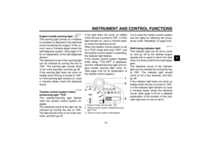 23
23 24
24 25
25 26
26 27
27 28
28 29
29 30
30 31
31 32
32 33
33 34
34 35
35 36
36 37
37 38
38 39
39 40
40 41
41 42
42 43
43 44
44 45
45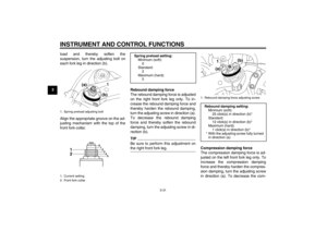 46
46 47
47 48
48 49
49 50
50 51
51 52
52 53
53 54
54 55
55 56
56 57
57 58
58 59
59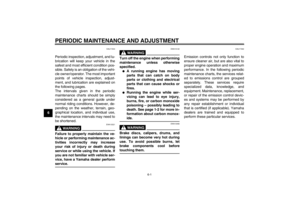 60
60 61
61 62
62 63
63 64
64 65
65 66
66 67
67 68
68 69
69 70
70 71
71 72
72 73
73 74
74 75
75 76
76 77
77 78
78 79
79 80
80 81
81 82
82 83
83 84
84 85
85 86
86 87
87 88
88 89
89 90
90 91
91 92
92 93
93 94
94 95
95 96
96 97
97 98
98 99
99 100
100 101
101 102
102 103
103 104
104 105
105 106
106 107
107 108
108 109
109 110
110 111
111