Page 57 of 168

3-14
CHASSIS
CLEANING THE FRONT FORK OIL
SEAL AND DUST SEAL
1. Remove:
•Protector
• Dust seal "1"
Use a thin screw driver, and be care-
ful not to damage the inner fork tube
and dust seal.
2. Clean:
• Dust seal "a"
• Oil seal "b"
• Clean the dust seal and oil seal af-
ter every run.
• Apply the lithium soap base grease
on the inner tube.
RELIEVING THE FRONT FORK
INTERNAL PRESSURE
If the front fork initial movement feels
stiff during a run, relieve the front fork
internal pressure.
1. Elevate the front wheel by placing
a suitable stand under the engine.
2. Remove the air bleed screw "1"
and release the internal pressure
from the front fork.
3. Install:
• Air bleed screwADJUSTING THE FRONT FORK
REBOUND DAMPING FORCE
1. Adjust:
• Rebound damping force
By turning the adjuster "1".
• STANDARD POSITION:
This is the position which is back
by the specific number of clicks
from the fully turned-in position.
Do not force the adjuster past the
minimum or maximum extent of
adjustment. The adjuster may be
damaged.
Always adjust each front fork to
the same setting. Uneven adjust-
ment can cause poor handling and
loss of stability.
ADJUSTING THE FRONT FORK
COMPRESSION DAMPING FORCE
1. Adjust:
• Compression damping force
By turning the adjuster "1".• STANDARD POSITION:
This is the position which is back
by the specific number of clicks
from the fully turned-in position.
Do not force the adjuster past the
minimum or maximum extent of
adjustment. The adjuster may be
damaged.
Always adjust each front fork to
the same setting. Uneven adjust-
ment can cause poor handling and
loss of stability.
CHECKING THE REAR SHOCK
ABSORBER
1. Inspect:
• Swingarm smooth action
Abnormal noise/unsmooth action
→Grease the pivoting points or
repair the pivoting points.
Damage/oil leakage→Replace.
ADJUSTING THE REAR SHOCK
ABSORBER SPRING PRELOAD
1. Elevate the rear wheel by placing
the suitable stand under the en-
gine.
2. Remove:
• Rear frame Air bleed screw:
1 Nm (0.1 m•kg, 0.7
ft•lb)
Stiffer "a" →Increase the re-
bound damping force. (Turn
the adjuster "1" in.)
Softer "b" →Decrease the re-
bound damping force. (Turn
the adjuster "1" out.)
Extent of adjustment:
Maximum Minimum
Fully turned in
position20 clicks out
(from maximum
position)
Standard position:
14 clicks out
* 13 clicks out
* For EUROPE
Stiffer "a" →Increase the com-
pression damping force. (Turn
the adjuster "1" in.)
Softer "b" →Decrease the com-
pression damping force. (Turn
the adjuster "1" out.)
Extent of adjustment:
Maximum Minimum
Fully turned in
position20 clicks out
(from maximum
position)
Standard position:
13 clicks out
* 12 clicks out
* For EUROPE
Page 58 of 168

3-15
CHASSIS
3. Measure:
• Spring fitting length
• The I.D. mark "a" is marked at the
end of the spring.
• Spring specification varies accord-
ing to the difference in the produc-
tion lot.
4. Adjust:
• Spring preload
Adjustment steps:
a. Loosen the locknut "1".
b. Loosen the adjuster "2" until there
is some clearance between the
spring and adjuster.
c. Measure the spring free length
"a".
d. Turn the adjuster "2".
• Be sure to remove all dirt and mud
from around the locknut and adjust-
er before adjustment.
• The length of the spring (installed)
changes 1.5 mm (0.06 in) per turn
of the adjuster.
Never attempt to turn the adjuster
beyond the maximum or minimum
setting.
e. Tighten the locknut.
5. Install:
• Rear frame (upper)
• Rear frame (lower)
ADJUSTING THE REAR SHOCK
ABSORBER REBOUND DAMPING
FORCE
1. Adjust:
• Rebound damping force
By turning the adjuster "1".• STANDARD POSITION:
This is the position which is back
by the specific number of clicks
from the fully turned-in position.
(Which align the punch mark "a"
on the adjuster with the punch
mark "b" on the bracket.)
Do not force the adjuster past the
minimum or maximum extent of
adjustment. The adjuster may be
damaged.
ADJUSTING THE REAR SHOCK
ABSORBER LOW COMPRESSION
DAMPING FORCE
1. Adjust:
• Low compression damping force
By turning the adjuster "1". Standard fitting length:
I.D. MARK/
Q'TYLength
Red/1
Red/2
Red/3258 mm
(10.16 in)
*252 mm
(9.92 in)
264 mm
(10.39 in)
*258 mm
(10.16 in)
255.5 mm
(10.06 in)
*249.5 mm
(9.82 in)
*For EUROPE
Stiffer →Increase the spring pre-
load. (Turn the adjuster "2" in.)
Softer→Decrease the spring pre-
load. (Turn the adjuster "2"
out.)
Extent of adjustment:
Maximum Minimum
Position in
which the
spring is turned
in 18 mm (0.71
in) from its free
length.Position in
which the
spring is turned
in 1.5 mm (0.06
in) from its free
length.
Locknut:
30 Nm (3.0 m•kg, 22
ft•lb)
Rear frame (upper):
32 Nm (3.2 m•kg, 23
ft•lb)
Rear frame (lower):
29 Nm (2.9 m•kg, 21
ft•lb)
Stiffer "a" →Increase the re-
bound damping force. (Turn
the adjuster "1" in.)
Softer "b" →Decrease the re-
bound damping force. (Turn
the adjuster "1" out.)
Extent of adjustment:
Maximum Minimum
Fully turned in
position20 clicks out
(from maximum
position)
Standard position:
10–13 clicks out
* 11–14 clicks out
* For EUROPE
Stiffer "a" →Increase the low
compression damping force.
(Turn the adjuster "1" in.)
Softer "b" →Decrease the low
compression damping force.
(Turn the adjuster "1" out.)
Extent of adjustment:
Maximum Minimum
Fully turned in
position20 clicks out
(from maximum
position)
Page 59 of 168

3-16
CHASSIS
• STANDARD POSITION:This is the position which is back
by the specific number of clicks
from the fully turned-in position.
(Which align the punch mark "a"
on the adjuster with the punch
mark "b" on the high compression
damping adjuster.)
Do not force the adjuster past the
minimum or maximum extent of
adjustment. The adjuster may be
damaged.
ADJUSTING THE REAR SHOCK
ABSORBER HIGH COMPRESSION
DAMPING FORCE
1. Adjust:• High compression damping forceBy turning the adjuster "1". • STANDARD POSITION:
This is the position which is back
by the specific number of turns
from the fully turned-in position.
(Which align the punch mark "a"
on the adjuster with the punch
mark "b" on the adjuster body.)
Do not force the adjuster past the
minimum or maximum extent of
adjustment. The adjuster may be
damaged.
CHECKING THE TIRE PRESSURE
1. Measure:• Tire pressureOut of specification →Adjust.
• Check the tire while it is cold.
• Loose bead stoppers allow the tire
to slip off its position on the rim
when the tire pressure is low.
• A tilted tire valve stem indicates that
the tire slips off its position on the
rim.
• If the tire valve stem is found tilted, the tire is considered to be slipping
off its position. Correct the tire posi-
tion.
CHECKING AND TIGHTENING THE
SPOKES
The following procedure applies to all
of the spokes.
1. Check:• Spokes
Bend/damage →Replace.
Loose spoke →Retighten.
Tap the spokes with a screw-
driver.
A tight spoke will emit a clear, ringing
tone; a loose spoke will sound flat.
2. Tighten: • Spokes(with a spoke nipple wrench "1")
Be sure to tighten the spokes before
and after break-in.
CHECKING THE WHEELS
1. Inspect:• Wheel runoutElevate the wheel and turn it.
Abnormal runout → Replace.
2. Inspect: • Bearing free playExist play →Replace.
Standard position:
About 13 clicks out
Stiffer "a" →Increase the high
compression damping force.
(Turn the adjuster "1" in.)
Softer "b" →Decrease the high
compression damping force.
(Turn the adjuster "1" out.)
Extent of adjustment:
Maximum Minimum
Fully turned in
position 2 turns out
(from maximum
position)
Standard position:
About 1-1/2 turns out
Standard tire pressure: 100 kPa (1.0 kgf/cm
2,
15 psi)
Spoke nipple wrench: YM-01521/90890-01521
Spokes: 3 Nm (0.3 m•kg, 2.2
ft•lb)
Page 60 of 168

3-17
CHASSIS
CHECKING AND ADJUSTING THE
STEERING HEAD
1. Place a stand under the engine to
raise the front wheel off the
ground. WARNING! Securely
support the vehicle so that
there is no danger of it falling
over.
2. Check:
• Steering stem
Grasp the bottom of the forks and
gently rock the fork assembly
back and forth.
Free play→Adjust steering head.
3. Check:
• Steering smooth action
Turn the handlebar lock to lock.
Unsmooth action→Adjust steer-
ing ring nut.
4. Adjust:
• Steering ring nut
Steering ring nut adjustment
steps:
a. Remove the number plate.
b. Remove the handlebar and upper
bracket.
c. Loosen the steering ring nut "1"
using the steering nut wrench "2".
d. Tighten the steering ring nut "3"
using steering nut wrench "4".
• Apply the lithium soap base grease
on the thread of the steering stem.
• Set the torque wrench to the steer-
ing nut wrench so that they form a
right angle.
e. Loosen the steering ring nut one
turn.
f. Retighten the steering ring nut us-
ing the steering nut wrench.
Avoid over-tightening.
g. Check the steering stem by turn-
ing it lock to lock. If there is any
binding, remove the steering stem
assembly and inspect the steer-
ing bearings.
h. Install the washer "5", upper
bracket "6", washer "7", steering
stem nut "8", handlebar "9", han-
dlebar upper holder "10" and
number plate "11".
• The handlebar upper holder should
be installed with the punched mark
"a" forward.
• Install the handlebar so that the
marks "b" are in place on both
sides.
• Install the handlebar so that the pro-
jection "c" of the handlebar upper
holder is positioned at the mark on
the handlebar as shown.
• Insert the end of the fuel breather
hose "12" into the hole in the steer-
ing stem.
First tighten the bolts on the front
side of the handlebar upper holder,
and then tighten the bolts on the
rear side.
Steering nut wrench:
YU-33975/90890-01403
Steering nut wrench:
YU-33975/90890-01403
Steering ring nut (initial
tightening):
38 Nm (3.8 m•kg, 27
ft•lb)
Steering ring nut (final
tightening):
7 Nm (0.7 m•kg, 5.1
ft•lb)Steering stem nut:
145 Nm (14.5 m•kg, 105
ft•lb)
Handlebar upper holder:
28 Nm (2.8 m•kg, 20
ft•lb)
Pinch bolt (upper brack-
et):
21 Nm (2.1 m•kg, 15
ft•lb)
Number plate:
7 Nm (0.7 m•kg, 5.1
ft•lb)
Page 61 of 168
3-18
CHASSIS
LUBRICATION
To ensure smooth operation of all
components, lubricate your machine
during setup, after break-in, and after
every race.
1. All control cable
2. Clutch lever pivot
3. Shift pedal pivot
4. Footrest pivot
5. Throttle-to-handlebar contact
6. Drive chain7. Throttle roller cable guide
8. Throttle roller sliding surface
9. Tube guide cable winding por-
tion
10. Throttle cable end
11. Clutch cable end
A. Use Yamaha cable lube or
equivalent on these areas.
B. Use SAE 10W-40 motor oil or
suitable chain lubricants.C. Lubricate the following areas
with high quality, lightweight lith-
ium-soap base grease.
Wipe off any excess grease, and
avoid getting grease on the brake
discs.
Page 62 of 168

3-19
ELECTRICAL
ELECTRICAL
CHECKING THE SPARK PLUG
1. Remove:
• Spark plug
2. Inspect:
• Electrode "1"
Wear/damage→Replace.
• Insulator color "2"
Normal condition is a medium to
light tan color.
Distinctly different color→Check
the engine condition.
When the engine runs for many hours
at low speeds, the spark plug insula-
tor will become sooty, even if the en-
gine and carburetor are in good
operating condition.
3. Measure:
• Plug gap "a"
Use a wire gauge or thickness
gauge.
Out of specification→Regap.
4. Clean the plug with a spark plug
cleaner if necessary.
5. Tighten:
• Spark plug
• Before installing a spark plug, clean
the gasket surface and plug sur-
face.
• Finger-tighten "a" the spark plug
before torquing to specification "b".
CHECKING THE IGNITION TIMING
1. Remove:
•Fuel tank
Refer to "SEAT, FUEL TANK
AND SIDE COVERS" section in
the CHAPTER 4.
• Spark plug
• Crankcase cover (left)
2. Attach:
• Dial gauge "1"
• Spark plug hole dial stand "2"
3. Rotate the magneto rotor "1" until
the piston reaches top dead cen-
ter (TDC). When this happens,
the needle on the dial gauge will
stop and reverse directions even
though the rotor is being turned in
the same direction.
4. Set the dial gauge to zero at TDC.
5. From TDC, rotate the rotor clock-
wise until the dial gauge indicates
that the piston is at a specified
distance from TDC.
6. Check:
• Ignition timing
Punch mark "a" on rotor should be
aligned with punch mark "b" on
stator.
Not aligned→Adjust.7. Adjust:
• Ignition timing
Adjustment steps:
a. Loosen the screws (stator) "1".
b. Align the punch mark on the rotor
with punch mark on the stator "2"
by moving the stator.
c. Tighten the screws (stator).
Spark plug gap:
0.6–0.7 mm (0.024–
0.028 in)
Standard spark plug:
BR9EVX/NGK (resistance type)
Spark plug:
20 Nm (2.0 m•kg, 14
ft•lb)
Dial gauge:
YU-3097/90890-01252
Spark plug hole dial
stand:
YU-1256
Ignition timing (B.T.D.C.):
0.48 mm (0.019 in)
Screw (stator):
7 Nm (0.7 m•kg, 5.1
ft•lb)
Page 63 of 168

4-1
SEAT, FUEL TANK AND SIDE COVERS
ENGINE
This section is intended for those who have basic knowledge and skill concerning the servicing of Yamaha motorcycles
(e.g., Yamaha dealers, service engineers, etc.) Those who have little knowledge and skill concerning servicing are request-
ed not to undertake inspection, adjustment, disassembly, or reassembly only by reference to this manual. It may lead to
servicing trouble and mechanical damage.
SEAT, FUEL TANK AND SIDE COVERS
REMOVING THE SEAT, FUEL TANK AND SIDE COVERS
Order Part name Q'ty Remarks
Turn the fuel cock to "OFF".
Disconnect the fuel hose.
1Seat 1
2 Air scoop (left and right) 2
3 Fitting band 1 Remove on fuel tank side.
4 Bolt (fuel tank) 2
5 Fuel tank 1
6 Left side cover 1 Refer to removal section.
7 Right side cover 1 Refer to removal section.
8 Number plate 1 Refer to removal section.
19 Nm (1.9 m kg, 13 ft lb)
7 Nm (0.7 m kg, 5.1 ft lb)
7 Nm (0.7 m kg, 5.1 ft lb)
7 Nm (0.7 m kg, 5.1 ft lb)
7 Nm (0.7 m kg, 5.1 ft lb)
7 Nm (0.7 m kg, 5.1 ft lb)
7 Nm (0.7 m kg, 5.1 ft lb)
7 Nm (0.7 m kg, 5.1 ft lb)
19 Nm (1.9 m kg, 13 ft lb)
6 Nm (0.6 m kg, 4.3 ft lb)
6 Nm (0.6 m kg, 4.3 ft lb)
10 Nm (1.0 m kg, 7.2 ft lb)
4 Nm (0.4 m kg, 2.9 ft lb)
4
Page 64 of 168
4-2
SEAT, FUEL TANK AND SIDE COVERS
REMOVING THE SIDE COVER
1. Remove:
• Bolt (side cover)
• Side cover (left and right) "1"
Draw the side cover downward to re-
move it because its claws "a" are in-
serted in the air filter case.
REMOVING THE NUMBER PLATE
1. Remove:
• Bolt (number plate)
• Number plate "1"
• The projection "a" is inserted into
the band of the number plate. Pull
the band off the projection before
removal.
• Remove the clutch cable "2" from
the cable guide "b" on the number
plate.
• The projection "c" on the lower
bracket is inserted into the number
plate. Remove the number plate by
pulling it off the projection.
 1
1 2
2 3
3 4
4 5
5 6
6 7
7 8
8 9
9 10
10 11
11 12
12 13
13 14
14 15
15 16
16 17
17 18
18 19
19 20
20 21
21 22
22 23
23 24
24 25
25 26
26 27
27 28
28 29
29 30
30 31
31 32
32 33
33 34
34 35
35 36
36 37
37 38
38 39
39 40
40 41
41 42
42 43
43 44
44 45
45 46
46 47
47 48
48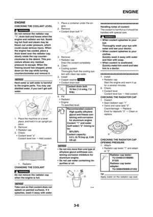 49
49 50
50 51
51 52
52 53
53 54
54 55
55 56
56 57
57 58
58 59
59 60
60 61
61 62
62 63
63 64
64 65
65 66
66 67
67 68
68 69
69 70
70 71
71 72
72 73
73 74
74 75
75 76
76 77
77 78
78 79
79 80
80 81
81 82
82 83
83 84
84 85
85 86
86 87
87 88
88 89
89 90
90 91
91 92
92 93
93 94
94 95
95 96
96 97
97 98
98 99
99 100
100 101
101 102
102 103
103 104
104 105
105 106
106 107
107 108
108 109
109 110
110 111
111 112
112 113
113 114
114 115
115 116
116 117
117 118
118 119
119 120
120 121
121 122
122 123
123 124
124 125
125 126
126 127
127 128
128 129
129 130
130 131
131 132
132 133
133 134
134 135
135 136
136 137
137 138
138 139
139 140
140 141
141 142
142 143
143 144
144 145
145 146
146 147
147 148
148 149
149 150
150 151
151 152
152 153
153 154
154 155
155 156
156 157
157 158
158 159
159 160
160 161
161 162
162 163
163 164
164 165
165 166
166 167
167

• Side cover (left and right) \"1\"
Draw the side cover downward to re-
move it because its claws \"a\" are i")