Page 49 of 168

3-6
ENGINE
ENGINE
CHECKING THE COOLANT LEVEL
Do not remove the radiator cap
"1", drain bolt and hoses when the
engine and radiator are hot. Scald-
ing hot fluid and steam may be
blown out under pressure, which
could cause serious injury. When
the engine has cooled, place a
thick towel over the radiator cap,
slowly rotate the cap counter-
clockwise to the detent. This pro-
cedure allows any residual
pressure to escape. When the
hissing sound has stopped, press
down on the cap while turning
counterclockwise and remove it.
Hard water or salt water is harmful
to the engine parts. You may use
distilled water, if you can't get soft
water.
1. Place the machine on a level
place, and hold it in an upright po-
sition.
2. Remove:
• Radiator cap
3. Check:
• Coolant level "a"
Coolant level low→Add coolant.
1. Radiator
CHANGING THE COOLANT
Do not remove the radiator cap
when the engine is hot.
Take care so that coolant does not
splash on painted surfaces. If it
splashes, wash it away with water.
1. Place a container under the en-
gine.
2. Remove:
• Coolant drain bolt "1"
3. Remove:
• Radiator cap
Drain the coolant completely.
4. Clean:
• Cooling system
Thoroughly flush the cooling sys-
tem with clean tap water.
5. Install:
• Copper washer
• Coolant drain bolt
6. Fill:
• Radiator
•Engine
To specified level.
• Do not mix more than one type of
ethylene glycol antifreeze con-
taining corrosion inhibitors for
aluminum engine.
• Do not use water containing im-
purities or oil.
Handling notes of coolant:
The coolant is harmful so it should be
handled with special care.
• When coolant splashes to your
eye.
Thoroughly wash your eye with
water and see your doctor.
• When coolant splashes to your
clothes.
Quickly wash it away with water
and then with soap.
• When coolant is swallowed.
Quickly make him vomit and take
him to a doctor.
7. Install:
• Radiator cap
Start the engine and warm it up
for a several minutes.
8. Check:
• Coolant level
Coolant level low→Add coolant.
CHECKING THE RADIATOR CAP
1. Inspect:
• Seal (radiator cap) "1"
• Valve and valve seat "2"
Crack/damage→Replace.
Exist fur deposits "3" →Clean or
replace.
CHECKING THE RADIATOR CAP
OPENING PRESSURE
1. Attach:
• Radiator cap tester "1" and adapt-
er "2"
Apply water on the radiator cap seal.
Coolant drain bolt:
10 Nm (1.0 m•kg, 7.2
ft•lb)
Recommended coolant:
High quality ethylene
glycol anti-freeze con-
taining anti-corrosion
for aluminum engine
Coolant "1" and water
(soft water) "2" mixing ra-
tio:
50%/50%
Coolant capacity:
0.9 L (0.79 Imp qt, 0.95
US qt)
Radiator cap tester:
YU-24460-01/90890-
01325
Radiator cap tester
adapter:
YU-33984/90890-01352
Page 50 of 168

3-7
ENGINE
3. Radiator cap
2. Apply the specified pressure.
3. Inspect:
• Pressure
Impossible to maintain the speci-
fied pressure for 10 seconds→
Replace.
CHECKING THE COOLING
SYSTEM
1. Inspect:
• Coolant level
2. Attach:
• Radiator cap tester "1" and adapt-
er "2"
3. Apply the specified pressure.
• Do not apply pressure more than
specified pressure.
• Radiator should be filled fully.
4. Inspect:
• Pressure
Impossible to maintain the speci-
fied pressure for 10 seconds→
Repair.
•Radiator "1"
• Radiator hose joint "2"
Coolant leakage→Repair or re-
place.
• Radiator hose "3"
Swelling→Replace.ADJUSTING THE CLUTCH CABLE
FREE PLAY
1. Check:
• Clutch lever free play "a"
Out of specification→Adjust.
2. Adjust:
• Clutch lever free play
Clutch lever free play adjustment
steps:
a. Loosen the locknuts "1".
b. Turn the adjuster "2" until free
play "a" is within the specified lim-
its.
c. Tighten the locknuts.
• Before adjustment, expose the ad-
juster by moving the boot "3" and
cap "4" away.
• Make minute adjustment on the le-
ver side using the adjuster "5".
• After adjustment, check proper op-
eration of clutch lever.
3. Install:
• Cap "1"
•Boot "2"
Place the tip "a" of the cap in the boot.
ADJUSTING THE THROTTLE GRIP
FREE PLAY
1. Check:
• Throttle grip free play "a"
Out of specification→Adjust.
2. Adjust:
• Throttle grip free play
Adjustment steps:
a. Slide the adjuster cover.
b. Loosen the locknut "1".
c. Turn the adjuster "2" until the
specified free play is obtained.
d. Tighten the locknut.
Prior to adjusting throttle grip free
play, the engine idling speed should
be adjusted.
After adjusting the throttle grip
free play, turn the handlebar to the
right and to the left to ensure that
this does not cause the engine
idling speed to change.
Radiator cap opening
pressure:
95–125 kPa (0.95–1.25
kg/cm
2, 13.5–17.8 psi)
Radiator cap tester:
YU-24460-01/90890-
01325
Radiator cap tester
adapter:
YU-33984/90890-01352
Standard pressure:
180 kPa (1.8 kg/cm
2,
25.6 psi)
Clutch lever free play "a"
:
8–13 mm (0.31–0.51 in)
Locknut:
4 Nm (0.4 m•kg, 2.9
ft•lb)Throttle grip free play
"a":
3–5 mm (0.12–0.20 in)
Locknut:
7 Nm (0.7 m•kg, 5.1
ft•lb)
Page 51 of 168

3-8
ENGINE
LUBRICATING THE THROTTLE
1. Remove:
• Cap cover "1"
• Throttle cable cap "2"
2. Apply:
• Lithium soap base grease
On the throttle cable end "a", tube
guide cable winding portion "b"
and roller sliding surface "c".
3. Install:
• Throttle cable cap
• Cap cover
CLEANING THE AIR FILTER
ELEMENT
Proper air filter maintenance is the
biggest key to preventing premature
engine wear and damage.
Never run the engine without the
air filter element in place; this
would allow dirt and dust to enter
the engine and cause rapid wear
and possible engine damage.
1. Remove:
• Seat
• Fitting bolt "1"
• Washer "2"
• Air filter element "3"
• Air filter guide "4"2. Clean:
• Air filter element
Clean them with solvent.
After cleaning, remove the remaining
solvent by squeezing the element.
• Do not twist the element when
squeezing the element.
• Leaving too much of solvent in
the element may result in poor
starting.
3. Inspect:
• Air filter element
Damage→Replace.
4. Apply:
• Foam-air-filter oil or equivalent oil
to the element
Squeeze out the excess oil. Element
should be wet but not dripping.
5. Install:
• Air filter guide "1"
Align the projection "a" on filter guide
with the hole "b" in air filter element.
6. Apply:
• Lithium soap base grease
On the matching surface "a" on air
filter element.7. Install:
• Air filter element "1"
• Washer
• Fitting bolt
Align the projection "a" on filter guide
with the hole "b" in air filter case.
CHECKING THE TRANSMISSION
OIL LEVEL
1. Start the engine, warm it up for
several minutes and wait for five
minutes.
2. Place the machine on a level
place and hold it up on upright po-
sition by placing the suitable
stand under the engine.
3. Check:
• Transmission oil level
Transmission oil level checking
steps:
a. Remove the oil check bolt "1".
b. Inspect the oil level.
Be sure the machine is positioned
straight up when inspecting the oil
level.
Never attempt to remove the oil
check bolt just after high speed
operation. The heated oil could
spout out, causing danger. Wait
until the oil cools down.
Oil flows out→Oil level is correct.
Oil does not flow out→Oil level is
low. Add transmission oil until oil
flows out. Throttle cable cap:
1 Nm (0.1 m•kg, 0.7
ft•lb)
Fitting bolt:
2 Nm (0.2 m•kg, 1.4
ft•lb)
Recommended brand:
YAMALUBE
Recommended engine
oil type
SAE10W-40
Recommended engine
oil grade
API service SG type or
higher
JASO standard MA
Page 52 of 168
,
replace if damaged.
d. Tighten the oil check bolt.
CHANGING THE TRANSMISSION
OIL
1. Start the engine and warm it up
for several minutes and wait")
3-9
CHASSIS
c. Inspect the gasket (oil check bolt),
replace if damaged.
d. Tighten the oil check bolt.
CHANGING THE TRANSMISSION
OIL
1. Start the engine and warm it up
for several minutes and wait for
five minute.
2. Place the machine on a level
place and hold it on upright posi-
tion by placing the suitable stand
under the engine.
3. Place a suitable container under
the engine.
4. Remove:
• Oil drain bolt "1"
• Oil filler cap "2"
Drain the transmission oil.
5. Install:
• Aluminum washer
• Oil drain bolt "1"6. Fill:
• Transmission oil
7. Check:
• Oil leakage
8. Check:
• Transmission oil level
9. Install:
• Oil filler cap "2"
ADJUSTING THE PILOT SCREW
1. Adjust:
• Pilot air screw "1"
Adjustment steps:
a. Screw in the pilot air screw until it
is lightly seated.
b. Back out by the specified number
of turns.
ADJUSTING THE ENGINE IDLING
SPEED
1. Start the engine and thoroughly
warm it up.
2. Adjust:
• Engine idling speed
Adjustment steps:
a. Loosen the locknut "1".
b. Turn the throttle stop screw "2"
until the engine runs at the lowest
possible speed.
c. Tighten the locknut.
CHECKING THE EXHAUST PIPE
1. Inspect:
• O-ring "1"
Damage→Replace.
Install the O-rings with their de-
pressed "a" facing outward.
CHASSIS
BLEEDING THE HYDRAULIC
BRAKE SYSTEM
Bleed the brake system if:
• The system has been disassem-
bled.
• A brake hose has been loosened
or removed.
• The brake fluid is very low.
• The brake operation is faulty.
A dangerous loss of braking per-
formance may occur if the brake
system is not properly bled.
1. Remove:
• Brake master cylinder cap
• Diaphragm
• Reservoir float (front brake)
• Protector (rear brake)
2. Bleed:
• Brake fluid
Air bleeding steps:
a. Add proper brake fluid to the res-
ervoir.
b. Install the diaphragm. Be careful
not to spill any fluid or allow the
reservoir to overflow.
c. Connect the clear plastic tube "2"
tightly to the caliper bleed screw
"1". Oil check bolt:
10 Nm (1.0 m•kg, 7.2
ft•lb)
Oil drain bolt:
20 Nm (2.0 m•kg, 14
ft•lb)
Recommended brand:
YAMALUBE
Recommended engine
oil type
SAE10W-40
Recommended engine
oil grade
API service SG type or
higher
JASO standard MA
Oil capacity (periodic oil
change):
0.66 L (0.58 Imp qt, 0.69
US qt)
Pilot air screw:
2-1/4 turns out
To increase idle speed→Turn the
throttle stop screw "2" in.
To decrease idle speed→Turn the
throttle stop screw "2" out.
Page 53 of 168

3-10
CHASSIS
A. Front
B. Rear
d. Place the other end of the tube
into a container.
e. Slowly apply the brake lever or
pedal several times.
f. Pull the lever in or push down on
the pedal. Hold the lever or pedal
in position.
g. Loosen the bleed screw and allow
the lever or pedal to travel to-
wards its limit.
h. Tighten the bleed screw when the
lever or pedal limit has been
reached; then release the lever or
pedal.
i. Repeat steps (e) to (h) until of the
air bubbles have been removed
from the system.
If bleeding is difficult, it may be nec-
essary to let the brake fluid system
stabilize for a few hours. Repeat the
bleeding procedure when the tiny
bubbles in the system have disap-
peared.
j. Add brake fluid to the level line on
the reservoir.
Check the operation of the brake
after bleeding the brake system.
3. Install:
• Protector (rear brake)
• Reservoir float (front brake)
• Diaphragm
• Brake master cylinder capADJUSTING THE FRONT BRAKE
1. Check:
• Brake lever position "a"
2. Remove:
• Brake lever cover
3. Adjust:
• Brake lever position
Brake lever position adjustment
steps:
a. Loosen the locknut "1".
b. Turn the adjusting bolt "2" until the
lever position "a" is within speci-
fied position.
c. Tighten the locknut.
Be sure to tighten the locknut, as it
will cause poor brake perfor-
mance.
4. Install:
• Brake lever cover
ADJUSTING THE REAR BRAKE
1. Check:
• Brake pedal height "a"
Out of specification→Adjust.2. Adjust:
• Brake pedal height
Pedal height adjustment steps:
a. Loosen the locknut "1".
b. Turn the adjusting nut "2" until the
pedal height "a" is within specified
height.
c. Tighten the locknut.
• Adjust the pedal height between
the maximum "A" and the mini-
mum "B" as shown. (In this ad-
justment, the bolt "3" end "b"
should protrude out of the
threaded portion "4" but not be
less than 2 mm (0.08 in) "c" away
from the brake pedal "5").
• After the pedal height adjust-
ment, make sure that the rear
brake does not drag.
CHECKING AND REPLACING THE
FRONT BRAKE PADS
1. Inspect:
• Brake pad thickness "a"
Out of specification→Replace as
a set. Bleed screw:
6 Nm (0.6 m•kg, 4.3
ft•lb)
Brake lever position "a":
Standard posi-
tionExtent of ad-
justment
95 mm (3.74 in)86–105 mm
(3.39–4.13 in)
Locknut:
5 Nm (0.5 m •kg, 3.6
ft•lb)
Brake pedal height "a":
Zero mm (Zero in)
Brake pad thickness:
4.4 mm (0.17 in)
: 1.0 mm (0.04
in)
Page 54 of 168

3-11
CHASSIS
2. Replace:
• Brake pad
Brake pad replacement steps:
a. Remove the pad pin plug "1".
b. Loosen the pad pin "2".
c. Remove the brake caliper "3"
from the front fork.
d. Remove the pad pin and brake
pads "4".
e. Connect the transparent hose "5"
to the bleed screw "6" and place
the suitable container under its
end.
f. Loosen the bleed screw and push
the brake caliper piston in.
Do not reuse the drained brake flu-
id.
g. Tighten the bleed screw.
h. Install the brake pads "7" and pad
pin.
• Install the brake pads with their pro-
jections "a" into the brake caliper re-
cesses "b".
• Temporarily tighten the pad pin at
this point.
i. Install the brake caliper "8" and
tighten the pad pin "9".
j. Install the pad pin plug "10".
3. Inspect:
• Brake fluid level
Refer to "CHECKING THE
BRAKE FLUID LEVEL" section.
4. Check:
• Brake lever operation
A softy or spongy feeling→Bleed
brake system.
Refer to "BLEEDING THE HY-
DRAULIC BRAKE SYSTEM" sec-
tion.CHECKING AND REPLACING THE
REAR BRAKE PADS
1. Inspect:
• Brake pad thickness "a"
Out of specification→Replace as
a set.
2. Replace:
• Brake pad
Brake pad replacement steps:
a. Remove the protector "1" and pad
pin plug "2".
b. Loosen the pad pin "3".
c. Remove the rear wheel "4" and
brake caliper "5".
Refer to "FRONT WHEEL AND
REAR WHEEL" section in the
CHAPTER 5.
d. Remove the pad pin "6" and brake
pads "7".
Bleed screw:
6 Nm (0.6 m•kg, 4.3
ft•lb)
Bolt (brake caliper):
28 Nm (2.8 m•kg, 20
ft•lb)
Pad pin:
18 Nm (1.8 m•kg, 13
ft•lb)
Pad pin plug:
3 Nm (0.3 m•kg, 2.2
ft•lb)
Brake pad thickness:
6.4 mm (0.25 in)
: 1.0 mm (0.04
in)
Page 55 of 168

3-12
CHASSIS
e. Connect the transparent hose "8"
to the bleed screw "9" and place
the suitable container under its
end.
f. Loosen the bleed screw and push
the brake caliper piston in.
Do not reuse the drained brake flu-
id.
g. Tighten the bleed screw.
h. Install the brake pad "10" and pad
pin "11".
• Install the brake pads with their pro-
jections "a" into the brake caliper re-
cesses "b".
• Temporarily tighten the pad pin at
this point.
i. Install the brake caliper "12" and
rear wheel "13".
Refer to "FRONT WHEEL AND
REAR WHEEL" section in the
CHAPTER 5.
j. Tighten the pad pin "14".k. Install the pad pin plug "15" and
protector "16".
3. Inspect:
• Brake fluid level
Refer to "CHECKING THE
BRAKE FLUID LEVEL" section.
4. Check:
• Brake pedal operation
A softy or spongy feeling→Bleed
brake system.
Refer to "BLEEDING THE HY-
DRAULIC BRAKE SYSTEM" sec-
tion.
CHECKING THE REAR BRAKE
PAD INSULATOR
1. Remove:
•Brake pad
Refer to "CHECKING AND RE-
PLACING THE REAR BRAKE
PADS" section.
2. Inspect:
• Rear brake pad insulator "1"
Damage→Replace.
CHECKING THE BRAKE FLUID
LEVEL
1. Place the brake master cylinder
so that its top is in a horizontal po-
sition.
2. Inspect:
• Brake fluid level
Fluid at lower level→Fill up.
• Use only designated quality
brake fluid to avoid poor brake
performance.
• Refill with same type and brand
of brake fluid; mixing fluids
could result in poor brake perfor-
mance.
• Be sure that water or other con-
taminants do not enter master
cylinder when refilling.
• Clean up spilled fluid immediate-
ly to avoid erosion of painted
surfaces or plastic parts.
a. Lower level
A. Front
B. Rear
CHECKING THE SPROCKET
1. Inspect:
• Sprocket teeth "a"
Excessive wear→Replace.
Replace the drive sprocket, rear
wheel sprocket and drive chain as a
set.
CHECKING THE DRIVE CHAIN
1. Measure:
• Drive chain length (15 links) "a"
Out of specification→Replace.
• While measuring the drive chain
length, push down on the drive
chain to increase its tension.
• Measure the length between drive
chain roller "1" and "16" as shown.
• Perform this measurement at two or
three different places.
Bleed screw:
6 Nm (0.6 m•kg, 4.3
ft•lb)
Pad pin:
18 Nm (1.8 m•kg, 13
ft•lb)
Pad pin plug:
3 Nm (0.3 m•kg, 2.2
ft•lb)
Bolt (protector):
7 Nm (0.7 m•kg, 5.1
ft•lb)
Recommended brake flu-
id:
DOT #4
Drive chain length (15
links):
: 242.9 mm
(9.563 in)
Page 56 of 168

3-13
CHASSIS
2. Remove:
• Master link clip
•Joint "1"
• Drive chain "2"
3. Clean:
• Drive chain
Place it in kerosene, and brush off
as much dirt as possible. Then re-
move the drive chain from the ker-
osene and dry the drive chain.
4. Check:
• Drive chain stiffness "a"
Clean and oil the drive chain and
hold as illustrated.
Stiff→Replace the drive chain.
5. Install:
• Drive chain "1"
•Joint "2"
• Master link clip "3"
Be sure to install the master link
clip to the direction as shown.
a. Turning direction6. Lubricate:
• Drive chain
ADJUSTING THE DRIVE CHAIN
SLACK
1. Elevate the rear wheel by placing
the suitable stand under the en-
gine.
2. Check:
• Drive chain slack "a"
Above the seal guard installation
bolt.
Out of specification→Adjust.
Before checking and/or adjusting, ro-
tate the rear wheel through several
revolutions and check the slack sev-
eral times to find the tightest point.
Check and/or adjust the drive chain
slack with the rear wheel in this "tight
chain" position.
3. Adjust:
• Drive chain slack
Drive chain slack adjustment
steps:
a. Loosen the axle nut "1" and lock-
nuts "2".
b. Adjust the drive chain slack by
turning the adjusters "3".c. Turn each adjuster exactly the
same amount to maintain correct
axle alignment. (There are marks
"a" on each side of the drive chain
puller alignment.) NOTICE: Im-
proper drive chain slack will
overload the engine as well as
other vital parts of the motorcy-
cle and can lead to chain slip-
page or breakage. To prevent
this from occurring, keep the
drive chain slack within the
specified limits.
Turn the adjuster so that the drive
chain is in line with the sprocket, as
viewed from the rear.
d. Tighten the axle nut while pushing
down the drive chain.
e. Tighten the locknuts.
CHECKING THE FRONT FORK
1. Inspect:
• Front fork smooth action
Operate the front brake and
stroke the front fork.
Unsmooth action/oil leakage→
Repair or replace.
Drive chain lubricant:
SAE 10W-40 motor oil
or suitable chain lubri-
cants
Drive chain slack:
48–58 mm (1.9–2.3 in)
To tighten→Turn the adjuster "3"
counterclockwise.
To loosen→Turn the adjuster "3"
clockwise and push wheel for-
ward.
Axle nut:
125 Nm (12.5 m•kg, 90
ft•lb)
Locknut:
19 Nm (1.9 m•kg, 13
ft•lb)
 1
1 2
2 3
3 4
4 5
5 6
6 7
7 8
8 9
9 10
10 11
11 12
12 13
13 14
14 15
15 16
16 17
17 18
18 19
19 20
20 21
21 22
22 23
23 24
24 25
25 26
26 27
27 28
28 29
29 30
30 31
31 32
32 33
33 34
34 35
35 36
36 37
37 38
38 39
39 40
40 41
41 42
42 43
43 44
44 45
45 46
46 47
47 48
48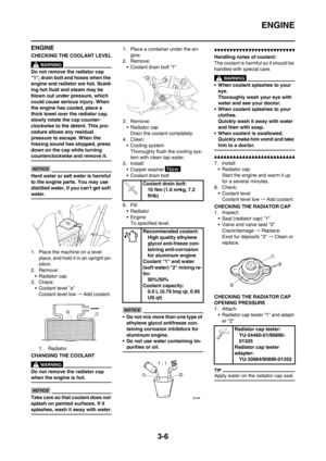 49
49 50
50 51
51 52
52 53
53 54
54 55
55 56
56 57
57 58
58 59
59 60
60 61
61 62
62 63
63 64
64 65
65 66
66 67
67 68
68 69
69 70
70 71
71 72
72 73
73 74
74 75
75 76
76 77
77 78
78 79
79 80
80 81
81 82
82 83
83 84
84 85
85 86
86 87
87 88
88 89
89 90
90 91
91 92
92 93
93 94
94 95
95 96
96 97
97 98
98 99
99 100
100 101
101 102
102 103
103 104
104 105
105 106
106 107
107 108
108 109
109 110
110 111
111 112
112 113
113 114
114 115
115 116
116 117
117 118
118 119
119 120
120 121
121 122
122 123
123 124
124 125
125 126
126 127
127 128
128 129
129 130
130 131
131 132
132 133
133 134
134 135
135 136
136 137
137 138
138 139
139 140
140 141
141 142
142 143
143 144
144 145
145 146
146 147
147 148
148 149
149 150
150 151
151 152
152 153
153 154
154 155
155 156
156 157
157 158
158 159
159 160
160 161
161 162
162 163
163 164
164 165
165 166
166 167
167