2012 YAMAHA XCITY 125 brake light
[x] Cancel search: brake lightPage 6 of 86

TABLE OF CONTENTSSAFETY INFORMATION ..................1-1
Further safe-riding points ................1-5
DESCRIPTION ..................................2-1
Left view ..........................................2-1
Right view ........................................2-2
Controls and instruments.................2-3
INSTRUMENT AND CONTROL
FUNCTIONS.......................................3-1
Immobilizer system .........................3-1
Main switch/steering lock ................3-2
Indicator lights and warning light ....3-3
Speedometer ..................................3-4
Fuel gauge ......................................3-5
Coolant temperature gauge ............3-5
Multi-function display ......................3-5
Handlebar switches ........................3-8
Front brake lever ............................3-9
Rear brake lever .............................3-9
Fuel tank cap ................................3-10
Fuel ...............................................3-10
Catalytic converters ......................3-12
Seat ..............................................3-12
Storage compartments .................3-13
Windshield ....................................3-14
Adjusting the shock absorber
assemblies ................................3-15
Carrier ...........................................3-16
Luggage hook ...............................3-16
Sidestand ......................................3-16Ignition circuit cut-off system ........ 3-17
FOR YOUR SAFETY –
PRE-OPERATION CHECKS............. 4-1
OPERATION AND IMPORTANT
RIDING POINTS................................. 5-1
Starting the engine ......................... 5-1
Starting off ...................................... 5-2
Acceleration and deceleration ........ 5-3
Braking ........................................... 5-3
Tips for reducing fuel
consumption ............................... 5-4
Engine break-in .............................. 5-4
Parking ........................................... 5-5
PERIODIC MAINTENANCE AND
ADJUSTMENT................................... 6-1
Owner’s tool kit ............................... 6-2
Periodic maintenance chart for the
emission control system ............. 6-3
General maintenance and
lubrication chart .......................... 6-4
Removing and installing cowlings
and panels .................................. 6-8
Checking the spark plug ................. 6-9
Engine oil ..................................... 6-10
Final transmission oil .................... 6-13
Coolant ......................................... 6-14
Air filter and V-belt case air filter
elements ................................... 6-15Checking the throttle grip free
play ........................................... 6-16
Valve clearance ........................... 6-17
Tires ............................................. 6-17
Cast wheels ................................. 6-19
Front and rear brake lever free
play ........................................... 6-19
Checking the front and rear brake
pads .......................................... 6-20
Checking the brake fluid level ...... 6-21
Changing the brake fluid .............. 6-22
Checking and lubricating the
cables ....................................... 6-22
Checking and lubricating the
throttle grip and cable ............... 6-23
Lubricating the front and rear
brake levers .............................. 6-23
Checking and lubricating the
centerstand and sidestand ....... 6-23
Checking the front fork ................. 6-24
Checking the steering .................. 6-25
Checking the wheel bearings ....... 6-25
Battery ......................................... 6-25
Replacing the fuses ..................... 6-27
Replacing a headlight bulb .......... 6-28
Replacing a front turn signal light
bulb ........................................... 6-29
Replacing a tail/brake light bulb or
a rear turn signal light bulb ....... 6-30
Replacing the license plate light
bulb ........................................... 6-31U16PE3E0.book Page 1 Tuesday, June 19, 2012 5:17 PM
Page 25 of 86

INSTRUMENT AND CONTROL FUNCTIONS
3-9
3
EAUS1020
Dimmer switch “ / ”
Set this switch to “ ” for the high
beam and to “ ” for the low beam.
With the headlight on low beam, press
this switch downwards to flash the
headlight.
EAU12460
Turn signal switch “ / ”
To signal a right-hand turn, push this
switch to “ ”. To signal a left-hand
turn, push this switch to “ ”. When re-
leased, the switch returns to the center
position. To cancel the turn signal
lights, push the switch in after it has re-
turned to the center position.
EAU12500
Horn switch “ ”
Press this switch to sound the horn.
EAU12721
Start switch “ ”
With the sidestand up, push this switch
while applying the front or rear brake to
crank the engine with the starter. See
page 5-1 for starting instructions prior
to starting the engine.
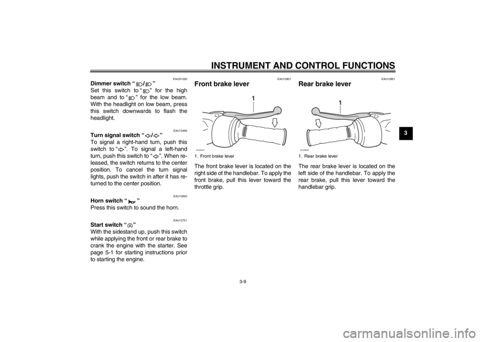
EAU12901
Front brake lever The front brake lever is located on the
right side of the handlebar. To apply the
front brake, pull this lever toward the
throttle grip.
EAU12951
Rear brake lever The rear brake lever is located on the
left side of the handlebar. To apply the
rear brake, pull this lever toward the
handlebar grip.
1. Front brake lever
1
ZAUM0791
1. Rear brake lever
1
ZAUM0085
U16PE3E0.book Page 9 Tuesday, June 19, 2012 5:17 PM
Page 33 of 86

INSTRUMENT AND CONTROL FUNCTIONS
3-17
3
WARNING
EWA10241
The vehicle must not be ridden with
the sidestand down, or if the side-
stand cannot be properly moved up
(or does not stay up), otherwise the
sidestand could contact the ground
and distract the operator, resulting
in a possible loss of control.
Yamaha’s ignition circuit cut-off
system has been designed to assist
the operator in fulfilling the respon-
sibility of raising the sidestand be-
fore starting off. Therefore, check
this system regularly and have a
Yamaha dealer repair it if it does not
function properly.
EAU45052
Ignition circuit cut-off system The ignition circuit cut-off system (com-
prising the sidestand switch and brake
light switches) has the following func-
tions.●
It prevents starting when the side-
stand is up, but neither brake is ap-
plied.
●
It prevents starting when either
brake is applied, but the sidestand
is still down.
●
It cuts the running engine when the
sidestand is moved down.
Periodically check the operation of the
ignition circuit cut-off system according
to the following procedure.
U16PE3E0.book Page 17 Tuesday, June 19, 2012 5:17 PM
Page 36 of 86

FOR YOUR SAFETY – PRE-OPERATION CHECKS
4-2
4
Rear brake Check operation.
If soft or spongy, have Yamaha dealer bleed hydraulic system.
Check brake pads for wear.
Replace if necessary.
Check fluid level in reservoir.
If necessary, add specified brake fluid to specified level.
Check hydraulic system for leakage.6-19, 6-20, 6-21
Throttle grip Make sure that operation is smooth.
Check throttle grip free play.
If necessary, have Yamaha dealer adjust throttle grip free play and lubricate cable
and grip housing.6-16, 6-23
Wheels and tires Check for damage.
Check tire condition and tread depth.
Check air pressure.
Correct if necessary.6-17, 6-19
Brake levers Make sure that operation is smooth.
Lubricate lever pivoting points if necessary.6-23
Centerstand, sidestand Make sure that operation is smooth.
Lubricate pivots if necessary.6-23
Chassis fasteners Make sure that all nuts, bolts and screws are properly tightened.
Tighten if necessary.—
Instruments, lights, signals
and switches Check operation.
Correct if necessary.—
Sidestand switch Check operation of ignition circuit cut-off system.
If system is not working correctly, have Yamaha dealer check vehicle.3-16 ITEM CHECKS PAGE
U16PE3E0.book Page 2 Tuesday, June 19, 2012 5:17 PM
Page 46 of 86

PERIODIC MAINTENANCE AND ADJUSTMENT
6-5
6
9*Steering bearings Check bearing play and steering
for roughness.√√√√√
Lubricate with lithium-soap-based
grease.Every 24000 km (14000 mi)
10*Chassis fasteners Make sure that all nuts, bolts and
screws are properly tightened.√√√√√
11Front brake lever
pivot shaft Lubricate with silicone grease.√√√√√
12Rear brake lever
pivot shaft Lubricate with silicone grease.√√√√√
13Sidestand, center-
stand Check operation.
Lubricate with lithium-soap-based
grease.√√√√√
14*Sidestand switch Check operation.√√√√√√
15*Front fork Check operation and for oil leak-
age.√√√√
16*Shock absorber as-
semblies Check operation and shock ab-
sorbers for oil leakage.√√√√
17 Engine oil Change. (See page 3-3.)√When the oil change indicator light comes on [5000 km (3000 mi)
after the initial 1000 km (600 mi) and every 6000 km (3500 mi)
thereafter]
Check oil level and vehicle for oil
leakage.Every 3000 km (1800 mi)√
18Engine oil filter ele-
ment Replace.√√√ NO. ITEM CHECK OR MAINTENANCE JOBODOMETER READING
ANNUAL
CHECK 1000 km
(600 mi)6000 km
(3500 mi)12000 km
(7000 mi)18000 km
(10500 mi)24000 km
(14000 mi)
U16PE3E0.book Page 5 Tuesday, June 19, 2012 5:17 PM
Page 47 of 86

PERIODIC MAINTENANCE AND ADJUSTMENT
6-6
6
EAU18670
TIP●
The air filter needs more frequent service if you are riding in unusually wet or dusty areas.
●
Hydraulic brake service
Regularly check and, if necessary, correct the brake fluid level.
Every two years replace the internal components of the brake master cylinders and calipers, and change the brake
fluid.
19*Cooling system Check coolant level and vehicle
for coolant leakage.√√√√√
Change coolant. Every 3 years
20Final transmission
oil Check vehicle for oil leakage.√√ √
Change.√√√
21*V- b e l t Replace. Every 18000 km (10500 mi)
22*Front and rear brake
switches Check operation.√√√√√√
23Moving parts and
cables Lubricate.√√√√√
24*Throttle grip Check operation.
Check throttle grip free play, and
adjust if necessary.
Lubricate cable and grip housing.√√√√√
25*Lights, signals and
switches Check operation.
Adjust headlight beam.√√√√√√ NO. ITEM CHECK OR MAINTENANCE JOBODOMETER READING
ANNUAL
CHECK 1000 km
(600 mi)6000 km
(3500 mi)12000 km
(7000 mi)18000 km
(10500 mi)24000 km
(14000 mi)
U16PE3E0.book Page 6 Tuesday, June 19, 2012 5:17 PM
Page 71 of 86

PERIODIC MAINTENANCE AND ADJUSTMENT
6-30
6 5. Insert a new bulb into the socket,
push it in, and then turn it clock-
wise until it stops.
6. Install the socket (together with the
bulb) by turning it clockwise.
7. Install the cowling.
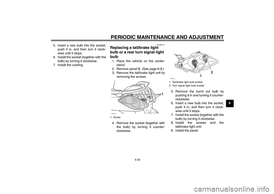
EAUM2191
Replacing a tail/brake light
bulb or a rear turn signal light
bulb 1. Place the vehicle on the center-
stand.
2. Remove panel B. (See page 6-8.)
3. Remove the tail/brake light unit by
removing the screws.
4. Remove the socket (together with
the bulb) by turning it counter-
clockwise.5. Remove the burnt out bulb by
pushing it in and turning it counter-
clockwise.
6. Insert a new bulb into the socket,
push it in, and then turn it clock-
wise until it stops.
7. Install the socket (together with the
bulb) by turning it clockwise.
8. Install the screws and the
tail/brake light unit.
9. Install the panel.1. ScrewZAUM0679
1
1. Tail/brake light bulb socket
2. Turn signal light bulb socketZAUM0680
12
U16PE3E0.book Page 30 Tuesday, June 19, 2012 5:17 PM
Page 76 of 86

SCOOTER CARE AND STORAGE
7-1
7
EAU26094
Care While the open design of a scooter re-
veals the attractiveness of the technol-
ogy, it also makes it more vulnerable.
Rust and corrosion can develop even if
high-quality components are used. A
rusty exhaust pipe may go unnoticed
on a car, however, it detracts from the
overall appearance of a scooter. Fre-
quent and proper care does not only
comply with the terms of the warranty,
but it will also keep your scooter looking
good, extend its life and optimize its
performance.
Before cleaning
1. Cover the muffler outlet with a
plastic bag after the engine has
cooled down.
2. Make sure that all caps and covers
as well as all electrical couplers
and connectors, including the
spark plug cap, are tightly in-
stalled.
3. Remove extremely stubborn dirt,
like oil burnt onto the crankcase,
with a degreasing agent and a
brush, but never apply such prod-ucts onto seals, gaskets and wheel
axles. Always rinse the dirt and de-
greaser off with water.
Cleaning
NOTICE
ECA10783
●
Avoid using strong acidic wheel
cleaners, especially on spoked
wheels. If such products are
used on hard-to-remove dirt, do
not leave the cleaner on the af-
fected area any longer than in-
structed. Also, thoroughly rinse
the area off with water, immedi-
ately dry it, and then apply a cor-
rosion protection spray.
●
Improper cleaning can damage
plastic parts (such as cowlings,
panels, windshields, headlight
lenses, meter lenses, etc.) and
the mufflers. Use only a soft,
clean cloth or sponge with wa-
ter to clean plastic. However, if
the plastic parts cannot be thor-
oughly cleaned with water, di-
luted mild detergent with water
may be used. Be sure to rinseoff any detergent residue using
plenty of water, as it is harmful
to plastic parts.
●
Do not use any harsh chemical
products on plastic parts. Be
sure to avoid using cloths or
sponges which have been in
contact with strong or abrasive
cleaning products, solvent or
thinner, fuel (gasoline), rust re-
movers or inhibitors, brake flu-
id, antifreeze or electrolyte.
●
Do not use high-pressure wash-
ers or steam-jet cleaners since
they cause water seepage and
deterioration in the following ar-
eas: seals (of wheel and swing-
arm bearings, fork and brakes),
electric components (couplers,
connectors, instruments,
switches and lights), breather
hoses and vents.
●
For scooters equipped with a
windshield: Do not use strong
cleaners or hard sponges as
they will cause dulling or
scratching. Some cleaning com-
pounds for plastic may leave
scratches on the windshield.
U16PE3E0.book Page 1 Tuesday, June 19, 2012 5:17 PM